- Clutch basket mounting bolts - 20 Nm
Warning! Dust - a product of wear of friction linings - may contain asbestos, which is hazardous to health. Do not blow it off with compressed air or inhale it. Do not use gasoline or gasoline-based solvents to remove dust. To remove dust, wash it into a suitable container with a special clutch cleaner or methanol.
The clutch can be removed if the entire power unit is dismantled and the gearbox is removed from it. It is also possible to remove the clutch when dismantling only the gearbox.
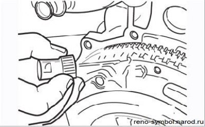
Figure 4.1. Marking the clutch cover and flywheel
In both cases, it is necessary to apply marks that determine the relative position of the clutch cover and the crankshaft flywheel (Figure 4.1).
Removing the clutch
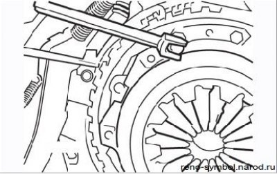
Figure 4.2. Removing the bolts securing the clutch cover to the flywheel
- block the flywheel with a wide-blade screwdriver and loosen the clutch cover mounting bolts in a diagonal sequence one to two turns per pass (Figure 4.2);
- remove the clutch cover from the guide bushings, being careful not to drop the clutch disc. Remember which side the disk is facing towards the flywheel;
- clean the clutch mechanism from dirt and dust, taking into account the warning at the beginning of the subsection.
Check as follows.
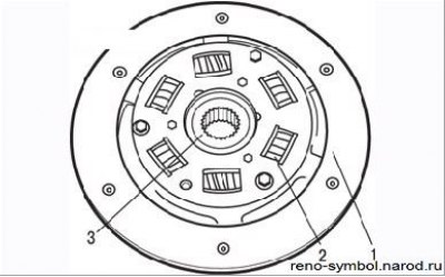
Figure 4.3. Check by external inspection of the condition of the clutch disc: 1 - friction lining; 2 - spring; 3 - hub
Inspect the contact surfaces of the clutch disc for signs of wear, damage to the springs and contamination. If the friction material is cracked, burnt, pitted, contaminated with dirt or oil (shiny black spots), worn out, replace the driven disc (Figure 4.3). Before installation, eliminate the source of oiling of the friction linings - it can be either the crankshaft oil seal or the gearbox input shaft oil seal.
It is better to entrust the replacement of the gearbox oil seal to the specialists of the Renault service center, since it will be necessary to disassemble the gearbox and remove the clutch release guide sleeve from the bearing using a press.
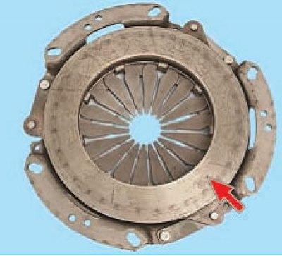
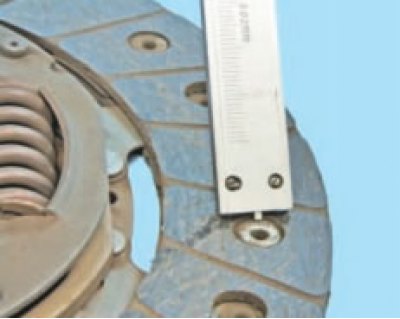
Figure 4.4. Checking the condition of the working surface of the pressure plate (arrow)
Check the machined surfaces of the flywheel and pressure plate. They must be absolutely even, smooth, without scuff marks, signs of overheating and cracks. If damage is found that cannot be repaired with sandpaper, replace parts (Figure 4.4).
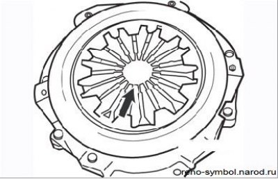
Figure 4.5. Check of a condition of petals of a diaphragm spring (arrow)
The petals of the diaphragm spring must be in the same plane and not have significant wear (Figure 4.5).
Check the clutch release bearing. It should rotate smoothly and easily, with no signs of noise or jamming; the contact surfaces must be smooth and undamaged, free of cracks, nicks and gouges. If you are in doubt about the good condition of the bearing, replace it.
Clutch installation
- clean the gearbox input shaft splines and apply a little MOLYKOTE BR2 grease to them;
- lubricate the clutch release bearing guide bush;
- When installing, make sure that the contact surfaces of the flywheel and discs are clean, flat, dry and free of oil. Use a solvent to remove dirt from the new kit. It is recommended to install the clutch with clean hands;
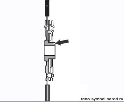
Figure 4.6. The protruding part of the hub of the driven disk must be turned towards the gearbox
- install the clutch disc onto the gearbox input shaft so that the protruding part of the driven disc hub faces the gearbox (Figure 4.6);
- install the clutch cover, aligning the bushings and marks previously applied during removal. Screw in the casing mounting bolts, tightening them only by hand so far, so that the driven disk can be displaced;
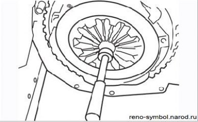
Figure 4.7. Centering the clutch disc with a mandrel
- center the driven disk using the mandrel supplied in the repair kit or made by yourself. To center the driven disc, move it slightly with a mandrel. Centering can be considered complete if the hole in the end of the crankshaft is located exactly in the middle of the hole in the hub of the driven disk (Figure 4.7);
- evenly tighten the clutch cover mounting bolts crosswise and tighten them to the required torque;
- remove the centering mandrel.
After installing the gearbox, connect the control cable to the release bearing yoke, adjust the cable.
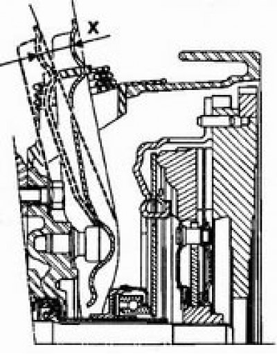
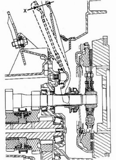
Check the clutch disengagement stroke: travel X should be 27.5-30.9 mm.
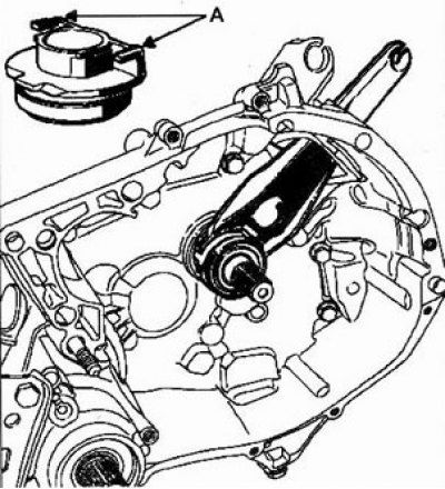
Note: With the gearbox installed, never raise the release bearing fork to prevent the fork from disengaging from the slots (A) bearing.
Special tool:
- Flywheel retainer - Mot. 582 or 582-01
Torque:
- Flywheel bolts - 20 Nm + 60°
Replacement
1. Remove the clutch.
2. Remove and discard the flywheel mounting bolts.
Note:
- Do not reinstall flywheel mounting bolts.
- Restoration of the flywheel surface by machining is not allowed.
3. Clean the threaded holes for installing the flywheel bolts in the crankshaft.
4. Remove grease from the bearing surface in the crankshaft.
5. Install the flywheel. Tighten the mounting bolts by hand.
6. Lock the flywheel with lock Mot. 582.
7. Tighten the bolts in diagonal sequence to 20 Nm and tighten them by 60°.
Note. The flywheel bolts must be replaced periodically.
Automatic wear compensation mechanism
Special remarks
The wear compensation sector is driven by the ratchet pin.
The ratchet should return to the zero position freely.
The cable at the clutch release fork has a slack of about 2 cm.
The total travel of the clutch release fork X is 27-30 mm.
Check the travel of the clutch release fork before tampering with the clutch system.