



Contents: Removal 🠛 Installation 🠛
Removal
Disconnect the wires from the battery terminals, starting with the negative terminal.
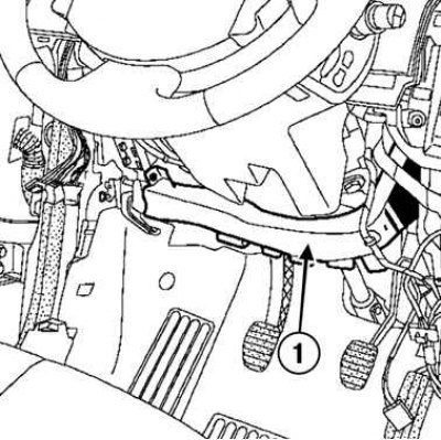
Fig. 3.6. Removing the air duct: 1 – air duct
Remove the left lower casing and air duct (Fig. 3.6).
Remove the gray start sensor by turning it a quarter turn.
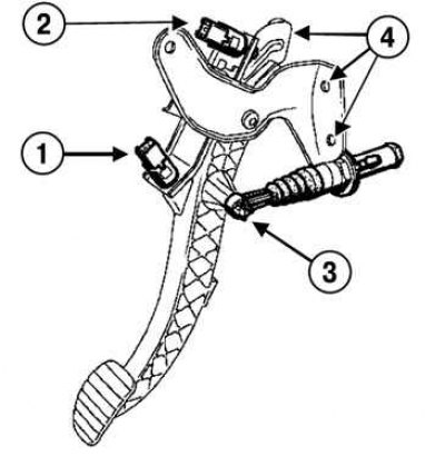
Fig. 3.7. Removing the clutch pedal: 1 – gray start sensor; 2 – green end of stroke sensor; 3 – ball head of the master cylinder; 4 – plate mounting nuts
Disconnect the wiring harness from the sensor (Fig. 3.7).
Remove the gray start sensor by turning it a quarter turn.
Disconnect the wiring harness from the sensor.
Remove the green end of stroke sensor by turning it a quarter turn.
Disconnect the wiring harness from the sensor.
Disconnect the master cylinder ball joint from the clutch pedal.
Disconnect the clutch pedal travel sensor connector.
Remove the clutch pedal travel sensor.
Remove the three clutch pedal assembly plate mounting nuts.
Remove the clutch pedal assembly.
Installation
Installation is carried out in the reverse order of removal.
Tighten the clutch pedal assembly plate mounting nuts to a torque of (21 N·m).
Be sure to pull on the sensor rods to select the adjustment gap.
The clutch pedal travel sensors are automatically adjusted depending on the pedal position.
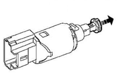
Fig. 3.8. Installing the clutch travel sensor
Install the sensors into their sockets (Fig. 3.8).
Turn the sensor a quarter turn clockwise.
Connect the clutch pedal sensor connectors.