



Contents: Ignition switch/steering column lock 🠛 Combination switches on the steering…🠛 Driver's side panel switches 🠛 Switches on the central panel 🠛 Front center console switches 🠛 Rear center console switches 🠛 Switches installed in the door 🠛 Switches on the overhead console 🠛 Switches on the seats 🠛 Brake light switch 🠛 Interior light switch 🠛 Trunk light switch 🠛
Note: Before removing any switch, disconnect the ground cable from the battery and reconnect after installing the switch.
Ignition switch/steering column lock
1. Insert the key into the ignition switch to lock the steering wheel.
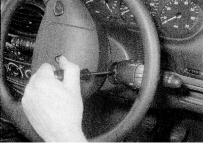
2. Turn the steering wheel so that you can access the radio switch. Remove the cover from the inside of the switch and loosen the screw securing the switch a few turns (refer to the accompanying illustration).
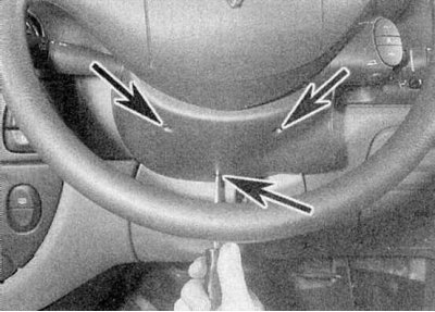
3a. Loosen the mounting screws.
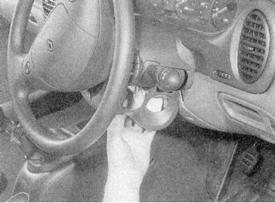
3b. Remove the lower steering column cover.
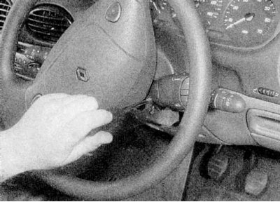
3c. Loosen the two mounting screws, turn the steering wheel as needed.
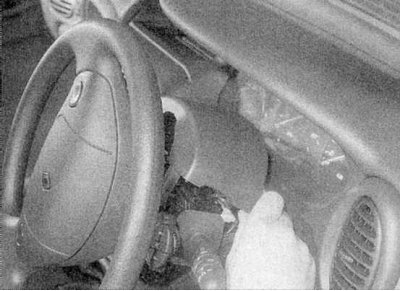
3d. Remove the upper steering column cover (refer to the illustrations).
4. Loosen the mounting screws and remove the lower cover under the steering column.
5. Follow the wiring from the switch and disconnect it from the main harness.
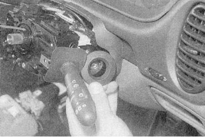
6a. Remove the trim from the lock.
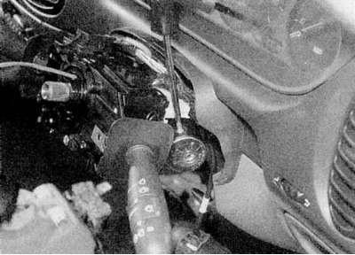
6b. Loosen the fastening screw (refer to the illustrations).
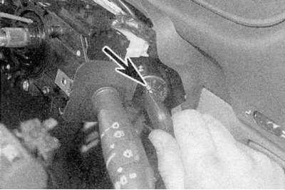
7a. Insert the ignition key and turn it until it is aligned with the mark between the switch positions "A" and "M".
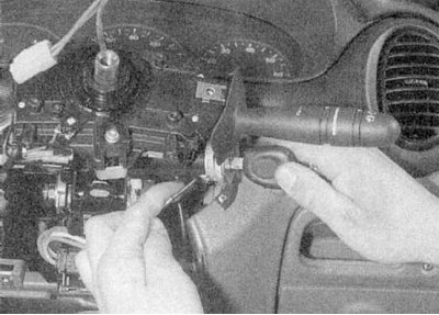
7b. Hold the key in this position, then press the retaining clip to remove the lock (refer to the illustrations).
8. Perform installation in reverse order.
Combination switches on the steering column
1. Remove the steering column covers as described in paragraphs 1 and 3 above.
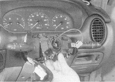
2. To remove one switch, disconnect the wiring, then loosen the mounting screws and slide the switch off the mounting bracket (refer to the accompanying illustration).
3. Before removing the complete switch assembly and mounting bracket, the steering wheel must be removed (refer to Chapter Suspension and steering); on airbag models, also remove the contact block. On all models, unscrew the radio switch mounting screw and move it to the side. Disconnect the wiring from the switches, then loosen the clamp screw a few turns and release the switch clamps. Remove the switch assembly from the steering column (refer to the accompanying illustration).
4. Install in reverse order. Securely connect all electrical wiring connectors. Before installing the steering wheel, make sure the switch levers are correctly positioned relative to the covers; if necessary, loosen the fastening screw, position the switch correctly and tighten the screw securely (refer to the accompanying illustration).
Driver's side panel switches
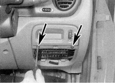
1. Remove the fuse box cover, then remove the screws securing the switch panel (refer to the accompanying illustration).
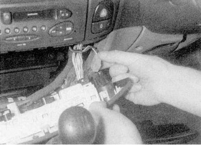
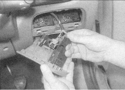
2a. Remove the switch panel.
2b. Disconnect the electrical wiring connectors (refer to the illustrations).
3. Install in reverse order.
Switches on the central panel
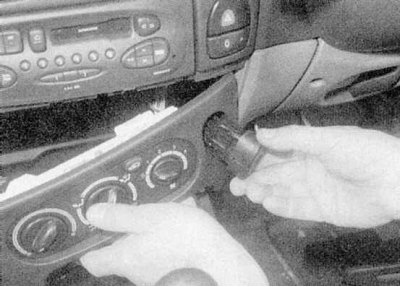
1. Remove the heater control panel (refer to Chapter Cooling and heating system).
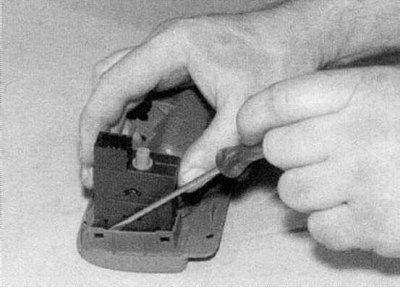
2a. Press the fastening brackets.
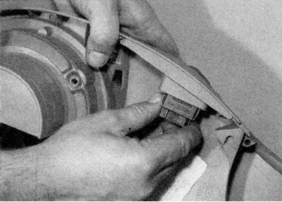
2b. Push out the corresponding switch and disconnect the wiring connector (refer to the illustrations).
3. Install in reverse order.
Front center console switches
All models except Scenic
1. Carefully pry the switch panel off and remove it from the center console, then disconnect the wiring connectors.
2. Loosen the screws securing the switch and remove it from the panel.
3. Install in reverse order.
Scenic Models
1. Remove the bolt securing the right footwell panel under the center of the instrument panel. Pull the front of the panel down to release the mounting pin, then push it forward to release the rear clips. Remove the left panel in the same manner.
2. Remove the switch panel from the center console by removing the two screws. Lift the panel up to release the brackets and alignment pins, then remove the unit. Disconnect the wiring connectors and remove the switch panel.
3. To remove the rear window switches, press the four tabs and push the switch out of the panel. To remove the remaining switches, remove the two mounting bolts.
4. Perform installation in reverse order.
Rear center console switches
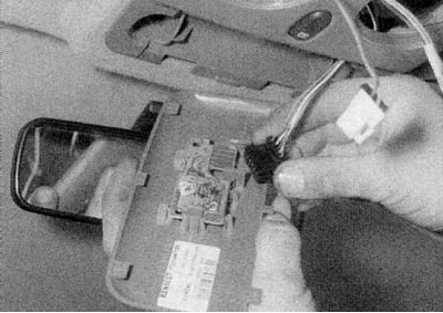
1. Carefully detach the switch panel from the rear of the center console and disconnect the wiring connectors (refer to the accompanying illustration).
2. Press the brackets and remove the switch, noting its location.
3. Install in reverse order.
Switches installed in the door
1. Remove the speaker from the door.
2. Loosen the mounting screws and remove the storage compartment for small items at the base of the door. Disconnect the electrical wiring connectors.
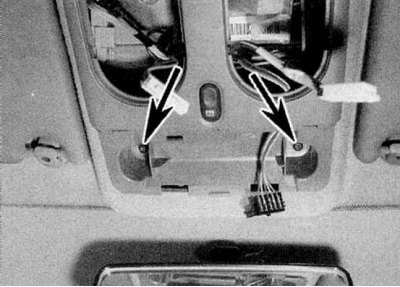
3. Press the fastening brackets and remove the switch (refer to the accompanying illustration).
4. Perform installation in reverse order.
Switches on the overhead console
1. Light switches are built into the interior lights (refer to Section Replacing lamps (interior lighting lights)). The switch can be removed for now as follows.
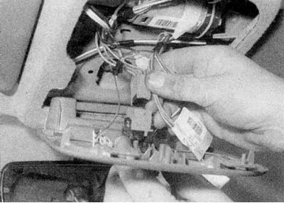
2. Slide the plastic cover forward from the overhead console (refer to the accompanying illustration).
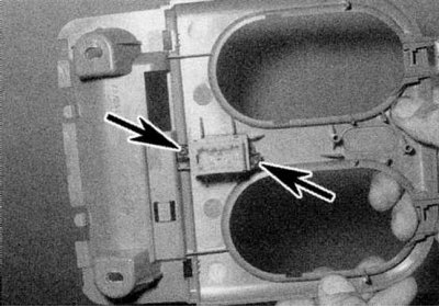
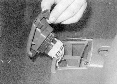
3a. Loosen the mounting screws.
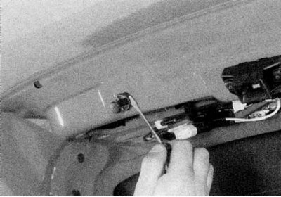
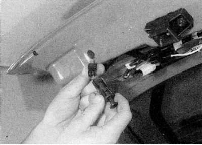
3b. Remove the switch assembly from the roof. Disconnect the wiring connectors (refer to the illustrations).
4. Loosen the mounting screws and remove the switch from the console (refer to the accompanying illustration).
5. Perform installation in reverse order.
Switches on the seats
1. Carefully remove the switch panel from the side of the seat using a screwdriver and disconnect it from the wiring connector.
2. Connect the electrical wiring connector and install the switch in place.
Brake light switch
1. Refer to Chapter Brake system.
Interior light switch
1. Open the door and remove the rubber cover from the switch.
2. Using a small flat-head screwdriver, press the switch's mounting brackets, then gently pull it out of the rack. Disconnect the wiring connector. Tape the wiring to the rack to prevent it from falling into the switch opening.
3. Reinstall in reverse order. Place the rubber cover on the switch and press it into place.
Trunk light switch
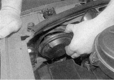
1a. Open the boot lid/tailgate.
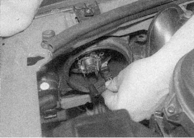
1b. Carefully remove the switch with a screwdriver and disconnect the wiring connector (refer to the illustrations).
2. Perform installation in reverse order.