General scheme of diagnostics
To save energy, the vehicle's UCH cuts off the power supply «+» after the ignition switch after 3 min.
To diagnose the computer, you can force the «+» after the ignition switch for 1 hour. To do this, do the following:
- press the card lock button;
- insert the card into the reader;
- click on the start button (exit feed mode «+» after ignition switch with time delay*);
- hold down the start button for 5 seconds until it starts flashing at a high frequency (4 Hz) signal lamp of the system of electronic anti-theft blocking of engine start.
This forced feed mode «+» after the ignition switch is valid for 1 hour. When you press the engine start button or remove the card from the reader, forced feeding «+» after the ignition switch stops, but the time delay of the forced feed mode «+» after the ignition switch continues to operate. Until the hour expires, when you turn on «+» after the castle «ignition» forced feed feeding mode «+» after the castle «ignition» reactivated for the remaining time.
Faults
Faults are defined as present or stored (appearing under certain conditions and then disappearing or continuing to occur, but not detectable under current conditions).
State «present fault» or «stored fault» should be considered when connecting the diagnostic tool after applying «+» after the castle «ignition» (without affecting the elements of this system).
If the fault is not confirmed, check:
- electrical circuits related to a faulty device or impaired function;
- connectors of these circuits (for signs of oxidation, bent terminals, etc.);
- resistance of a certain faulty element;
- wire condition (whether there is melted or cut insulation, traces of friction, etc.).
Troubleshooting algorithm
If no faults are found during the test with the scan tool, but the fault persists, then the fault should be corrected based on the complaint of the vehicle owner.
Wiring check (difficulties in diagnosis)
By disconnecting the connectors and/or moving the wiring harnesses, the cause of the malfunction can be corrected immediately.
Voltage, resistance and insulation resistance measurements usually give the correct measured values, especially if the fault is not present at the time of testing (is memorized).
Visual check
Look for signs of damage in the engine compartment and interior.
Carefully check the protective covers. the integrity of the insulation and the correct laying of the wiring harnesses.
Determine traces of oxidation.
Touch check
While wiggling or twisting the wire harnesses, use a scan tool to determine when the fault transitioned from «memorized» into a state «present».
Make sure the connectors are securely fixed.
Slightly «move» connectors.
Twist the wire harness.
If there has been a change in the state of the fault, try to determine its cause.
Checking individual elements
Disconnect the connectors and check the condition of the clamps and contacts, as well as their crimping (there should be no signs of compression on the insulation).
Check that the clips and contacts are securely fixed in the sockets of the connector.
Make sure that when connecting the connector, the clips and contacts are not squeezed out.
Check the contact pressure of the clamps using a suitable type of contact lead.
Resistance test
First check the integrity of the entire circuit, then in individual sections. Determine if there is a short circuit on «mass», at +12 V or with another wire.
If a fault is found, repair it or replace the wiring.
Security measures
During any work on the elements of the systems, it is necessary to follow the safety rules to prevent damage to the material part and injuries:
- make sure. that the battery is well charged in order to prevent malfunction of the computer if the battery is not sufficiently charged;
- use only serviceable and intended for this type of work equipment and devices.
Description of the injection system
The high pressure fuel injection system provides precisely metered fuel supply at a certain point in time.
ECU system 112-channel brand BOSCH and type EDC15C13.
The system includes:
- a manual booster pump or a booster electric pump in the low pressure circuit, if the engine is equipped with high-pressure fuel pump SRZ;
- booster electric pump, if the engine is equipped with high pressure fuel pump SR1;
- fuel filter;
- HPFP SR1 or SRZ;
- a high pressure control solenoid valve installed on the injection pump;
- fuel rail;
- fuel pressure sensor built into the rail;
- four electromagnetic nozzles;
- fuel temperature sensor;
- coolant temperature sensor;
- incoming air temperature sensor;
- camshaft position sensor;
- position and speed sensor of the engine crankshaft;
- boost pressure sensor;
- solenoid valve for exhaust gas recirculation;
- fuel pedal position sensor;
- atmospheric pressure sensor integrated in the injection computer;
- mass air flow sensor;
- boost pressure control solenoid valve;
- solenoid valve for controlling the pneumatic actuator of the engine stop damper;
- solenoid valve for controlling the pneumatic actuator of the swirl damper.
The common rail high pressure direct injection system is a sequential injection system based on the multipoint injection principle used in gasoline engines.
This injection system, thanks to the pre-injection method used in it, reduces engine noise, particulate matter and exhaust gas toxicity and provides significant engine torque, starting from a low engine speed.
The injection pump delivers fuel at high pressure to the fuel rail. The fuel regulator mounted on the pump regulates the amount of fuel supplied, the amount of which is set by the ECU. From the injection rail, fuel is supplied to the injectors through steel fuel lines.
ECU
The ECU determines the injection pressure required for normal engine operation and sends appropriate signals to the pressure regulator.
The ECU controls the pressure value based on the analysis of the signals issued by the fuel pressure sensor installed on the fuel distribution rail.
The ECU determines the injection duration required to supply sufficient fuel. and the moment of injection. After determining these two values, the ECU controls the operation of each injector individually by applying electrical signals.
The amount of fuel supplied to the engine is determined depending on the coolant:
- the duration of the control signal to the injector;
- pressure in the fuel rail. controlled injection computer;
- speed of opening and closing of the nozzle valve;
- injector valve needle stroke (constant value depends on the type of nozzles used);
- nominal hydraulic performance of the nozzle (unique to this injector).
The ECU controls:
- engine idle control;
- the amount of exhaust gases sent to the intake manifold;
- fuel supply (injection advance, fuel delivery and rail pressure);
- electric fan of the engine cooling system;
- operation of the air conditioning system (cooling capacity);
- regulator and speed limiter;
- pre- and post-start heating system;
- switching on signal lamps via the multiplex network.
Fuel is supplied to the injection pump at low pressure from the built-in fuel priming pump (transfer pump).
The injection pump delivers fuel to the fuel rail, the pressure in which is controlled during injection by the fuel supply regulator, and during draining by the injector valves. Thus, pressure fluctuations in the rail are smoothed out.
The fuel supply regulator ensures that the injection pump is supplied with the amount of fuel that is necessary to maintain rail pressure. Due to this, heat generation is reduced and engine output is improved.
To lower the pressure in the rail using the injector valves, short electrical impulses are applied to the valves:
- short enough not to cause the nozzle to open (passing through the drain circuit leaving the nozzles);
- long enough to open the valves and reduce the pressure in the rail.
Multiplex network communication between vehicle ECUs
The electronic systems installed on the vehicle are integrated together with the multiplex network. This ensures the exchange of information between the car's ECU. As a result:
- control of the inclusion of signal lamps of malfunctions on the instrument panel is carried out via a multiplex network;
- information about detected faults is received via the multiplex network;
- the speed sensor on the gearbox has been abolished.
Information about the vehicle speed is transmitted to the instrument panel via a wired connection from the ABS computer. and then from the instrument panel comes 8 multiplex network. The injection ECU and the airbag ECU are the main consumers of vehicle speed information.
Some vehicles are equipped with a water in fuel sensor located in the filter. If there is water in the fuel, the orange warning light for the injection system and the pre- and post-heating system will come on.
Attention! The engine must not be run when using diesel fuel containing more than 10% diester or gasoline, even in the smallest amount.
The system provides fuel injection under pressure up to 1350 bar. Before each operation, check that the fuel rail is not pressurized and that the fuel temperature is not too high.
When carrying out any work on the high pressure injection system, the cleanliness and safety instructions given in this document must be observed.
Disassembly of high pressure fuel pump and injectors is prohibited. Only the fuel regulator, fuel temperature sensor, and bypass valve need to be replaced.
For safety reasons, it is strictly forbidden to loosen the high pressure fuel line fittings while the engine is running.
To prevent contamination of the circuit, the pressure sensor must not be separated from the fuel rail. If the pressure sensor malfunctions, it is necessary to replace the sensor itself, the rail and the high pressure fuel lines.
It is strictly forbidden to remove the injection pump pulley with the number 070 575. If the pump is replaced, its pulley must also be replaced.
It is forbidden to apply +12 V supply voltage directly to any element of the system. It is forbidden to remove carbon deposits and clean with ultrasound.
Never start the engine if the battery is not properly connected. When carrying out welding work on the vehicle, disconnect the wire blocks from the injection computer.
Climate control
On vehicles with air conditioning, the EDC15 system makes it possible to deactivate the air conditioning via the UCH under certain operating conditions:
- if it is turned off by the driver;
- during engine start;
- when the engine overheats (to reduce the load on the engine);
- at very high engine speeds (to protect the compressor from destruction);
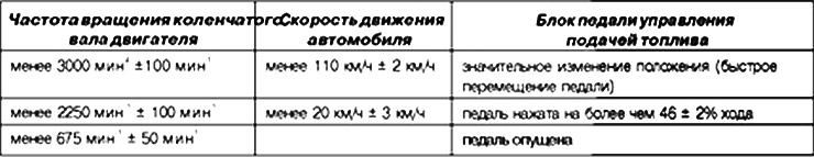
- in transitional modes (with a significant increase in the frequency of rotation of the crankshaft during overtaking, an increase in speed to prevent the engine from stopping and when starting off). These conditions are taken into account only if they are not of a periodic nature, in order to prevent violation of the stability of the system (spontaneous shutdowns);
- when some faults are found.
Control of the refrigeration circuit of the air conditioner
The control function of the refrigeration circuit of the air conditioner is distributed among several computers. The injection computer does the following:
- gives permission to turn on the air conditioner depending on the temperature of the coolant and engine speed;
- requests the engine cooling fan to turn on at low or high speed depending on the speed, coolant pressure and coolant temperature.
The driver turns on the air conditioner with a fan switch connected to the switch. Depending on the measured pressure value, this request for cooling the air entering the passenger compartment is fulfilled or not fulfilled. If the pressure value is outside the operating range, then the cooling capacity control algorithm is not activated.
The injection computer issues permission to turn on the air conditioner 2-8 seconds after the engine is started.
Compressor operation is prohibited under the following conditions.
Immersion heater control
To facilitate starting a cold engine, the car is equipped with immersion heaters.
The immersion heaters are controlled by the UCH. The injection computer issues permission or prohibition to turn on the heating elements, depending on the operating mode and the required engine power.
The number of simultaneously switched on heaters does not exceed four; their activation depends mainly on the temperature of the coolant and air.
Speed limiter and governor control
The speed control function provides, if enabled. maintaining the pre-selected vehicle speed regardless of driving conditions The driver can use the switches to increase or decrease the vehicle speed.
If desired, you can exceed the specified speed, for this:
- exceed the set speed by pressing the fuel control pedal (when the pedal is released, the original speed setting is automatically restored);
- press the system controls.
The speed control function can be disabled:
- system control switches;
- speed controller switch;
- upon detection of such control actions as pressing the brake or clutch pedal;
- when system errors are detected, including discrepancies between the set and actual speed.
The cruise control function may be temporarily disabled when the driver increases the vehicle speed by depressing the accelerator pedal. The set speed value is restored when the driver releases the accelerator pedal. In this case, the vehicle speed will gradually return to the set value.
After disabling the speed control function, you can re-enable the speed controller and restore the last speed setpoint (if the power to the computer is not turned off).
The speed limit function allows, when it is turned on, (switch) limit vehicle speed to a preselected level. The driver controls the speed of the vehicle with the fuel control pedal up to the set speed.
If the driver tries to exceed the set speed, the system does not react to the movement of the fuel control pedal and continues to maintain the set speed. as it happens when the speed controller is engaged, provided that the pedal is held down in a certain position.
As with the speed controller, you can change the speed setpoint by short or long pressing the switches.
For safety reasons, it is possible to exceed the set speed by depressing the throttle control pedal in such a way that the pedal moves beyond the limit speed limit position. In this case, the driving speed will be determined only by the position of the throttle pedal until the speed is below the set speed threshold, after which the speed limiting system is activated again.
If desired, you can exceed the specified speed, for this:
- press the fuel control pedal, overcoming the point of its resistance at the end of the stroke;
- set the desired speed limit by short or long pressing the pedal.
The speed limit feature can be disabled:
- system control switches;
- turning off the speed limiter;
- upon detection of such control actions as pressing the brake or clutch pedal;
- when system errors are detected, including discrepancies between the set and actual speed.
EGR control
The EGR system includes an EGR valve.
The system also includes a potentiometric valve position sensor.
The operation of the exhaust gas recirculation valve is controlled with feedback on the amount of air flow determined by the mass air flow sensor.
The potentiometric sensor is used to determine the position of the EGR valve.
Signal lamp control (indication on the instrument panel)
The ECU controls the display on the instrument panel of some information related to the operation of the engine. This applies to functions:
- signal lamp for pre- and post-heating;
- signaling the emergency temperature of the coolant;
- fault signaling of the 1st degree of severity (non-critical faults);
- fault signaling of the 2nd degree of severity (requiring an immediate stop);
- OBD warning light European OBD (EBSD).
These five kinds of functions are displayed by three signal lamps and/or as messages on the on-board computer.
Orange pre- and post-heating/minor warning light «SEFMCE» (1st degree of severity)
This signal lamp is used both as a lamp signaling the operation of the system and as an indicator of the presence of a malfunction in the system.
If the lamp is lit with a constant light when there is «+» after the ignition switch, this: means that the glow plugs are on.
If the lamp stays on and the message is displayed «injection a controler» («Check the injection system»): then this indicates the presence of a malfunction of the 1st degree of severity (the injection system goes into low efficiency mode).
The owner must rectify the fault as soon as possible.
Red signal lamp for emergency coolant temperature / immediate stop of movement «STOP» (2nd degree of severity)
This signal lamp is used both as a lamp that signals the operation of the system and as an indicator of the presence of a malfunction in the system: The lamp lights up for 3 seconds when turned on «ignition» (the automatic test procedure carried out by the instrument panel is carried out):
If the lamp stays on. this indicates that the engine is overheating (the driver has a choice: stop the car or continue driving).
Turning on the lamp with constant light is accompanied by the message «injection defaillante» («The injection system is faulty»): Indicates a 2nd degree fault (in this case fuel injection will automatically stop after a few seconds).
The owner must rectify the fault as soon as possible.
Orange signal lamp for exceeding the level of toxicity of exhaust gases allowed by the on-board diagnostic system (BSD)
This engine pictogram light comes on for about 3 seconds when turned on «ignition». This warning light will come on when there is one or more faults in the system detected by the OBD.
The malfunction warning light signals the driver that there is a malfunction in the injection system, leading to an increase in harmful emissions or that the on-board diagnostic system has been disabled (EOBD). The injection ECU sends a request to turn on the OBD warning light when there is a malfunction for three consecutive trips.
Visual control for 3 s when voltage is applied (instrument panel automatic test procedure) provided by the injection computer.
BBSD management
Onboard diagnostic system (On Board Diagnostic) detects malfunctions that reduce the effectiveness of vehicle emission control systems (exceeding OBD EURO IV toxicity standards).
This system must function properly throughout the life of the vehicle.
Conditions for detecting malfunctions by the on-board diagnostics
The on-board diagnostic system detects a malfunction after 3 vehicle driving cycles, while the following parameters are recorded in the computer memory:
- engine load;
- vehicle speed;
- air temperature;
- coolant temperature;
- boost pressure;
- pressure in the fuel distribution rail;
- air flow;
- vehicle mileage in km since the warning light was turned on «OBD (on-board diagnostic system)».
Thus, the driver receives information about the presence of a malfunction that directly affects the level of toxicity.
System Faults Detected by the On-Board Diagnostic System
The on-board diagnostic system detects only a few faults:
- DF038 «ECU»;
- DF040 «Cylinder No. 1 Injector Circuit» only with characteristic 2. DER
- DF041 «No. 2 injector circuit» only with characteristic 2. DER
- DF042 «No. 3 injector circuit» only with characteristic 2. DEF;
- DF043 «No. 4 cylinder injector circuit» only with characteristic 2. DER
- DF209 EGR valve position sensor circuit.
After some types of repair, it is necessary to perform programming to ensure the normal operation of some important elements of the system.
In particular, programming must be carried out if the EGR valve or injectors have been replaced.
Conditions for deleting from the memory of faults detected by the on-board diagnostic system
Deletion from the memory of faults detected by the on-board diagnostic system occurs in several stages.
A fault identified as present by the diagnostic tool becomes a stored fault (after repair) only after 3 vehicle cycles.
The OBD warning light goes out only after 3 driving cycles.
The lighting of the signal lamp 8 on the instrument panel does not in all cases indicate a malfunction in the system.
To delete from the memory of the ECU a malfunction detected by the on-board diagnostic system and the parameters of its appearance, it is necessary to perform 40 engine warm-up cycles.
An engine warm-up cycle is a vehicle driving cycle in which:
- the temperature of the coolant reaches a value of at least 71.1°C;
- the change in the temperature of the coolant relative to its value at the time of starting the engine is at least 22.2°C.
If one of the above conditions is not met, the fault is detected by the on-board diagnostic system. permanently stored in the memory of the injection computer as present or stored.
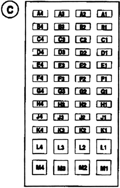
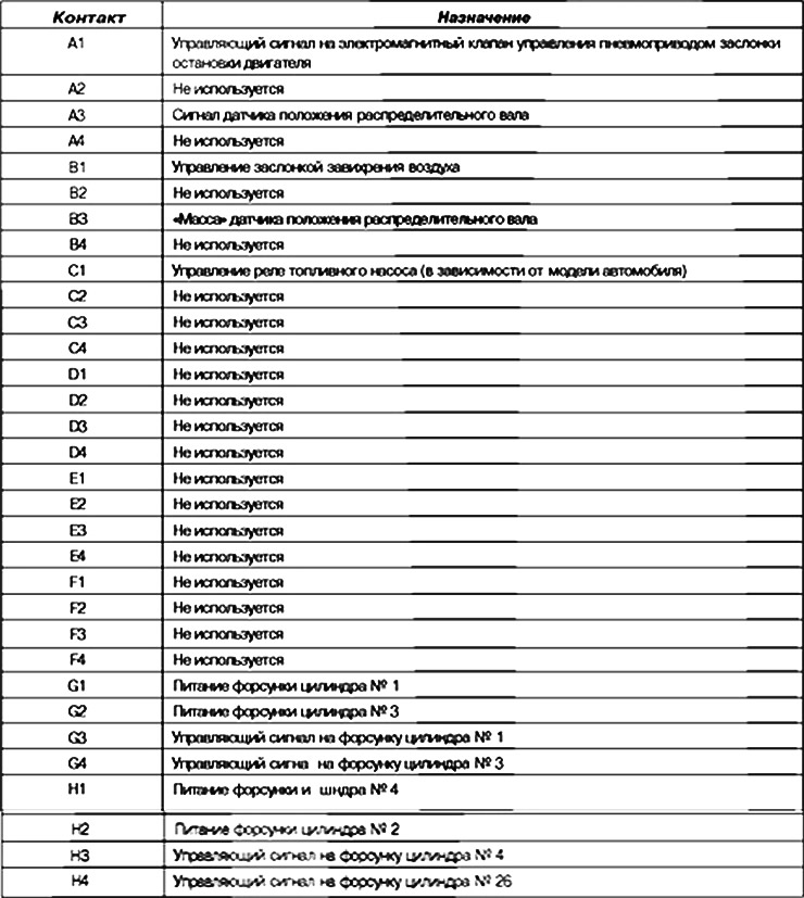
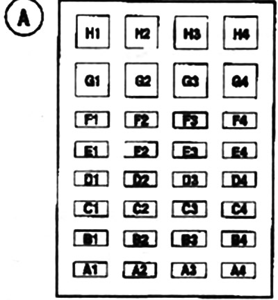
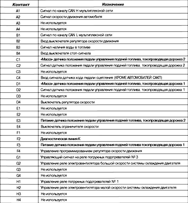
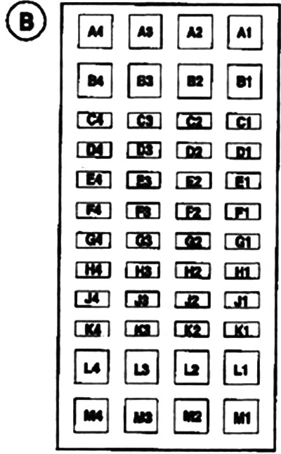
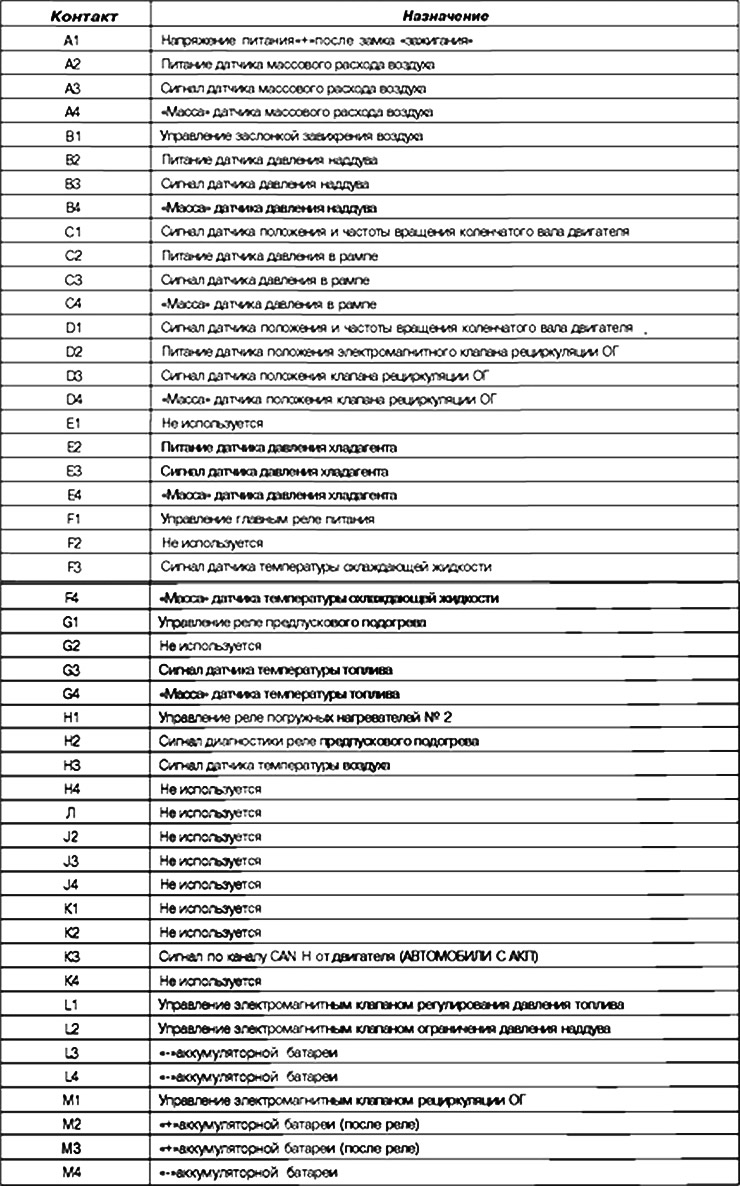
The purpose of the contacts of the diagnostic connectors of the computer
Black 32-pin connector A
48-pin B brown
32-pin gray C