



2. Check the headlight adjustment in the "0" position and adjust it if necessary.
3. Set the regulator to position "4".
4. The horizontal boundary of the light spot, when the headlight beam is correctly adjusted, should be 25 cm below the main installation line.
5. If this value is not reached, check if the headlight moves freely.
6. If the headlight movement is normal, check whether the spherical head of the servo motor is properly engaged in the headlight adjusting device.
7. Check the pin connections of the high beam adjustment regulator and the servo motor.
8. If everything is correct, measure the voltage between the two outer terminals.
9. The voltage should be 12 V.
10. Then measure the voltage between the middle and top terminals. Here, depending on the position of the regulator, the voltage should be between 2 and 12 V.
11. If the wires are in good condition, but the specified values are not achieved, then the high beam adjustment regulator is faulty.
12. If one of the two motors does not achieve the maximum possible headlight tilt, despite the correct voltage readings, the high beam adjustment servomotor must be replaced.
This note was copied from the resource www.renaultbook.ru
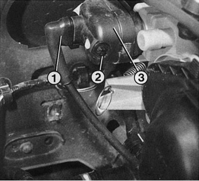
If the high beam adjustment servomotor (3) needs to be replaced, the connector (1) must be turned to release the bayonet lock. Carefully but firmly pull the spherical head off the reflector holder. The adjustment screw for the initial headlight adjustment is marked "2".
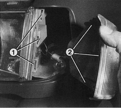
When installing the turn signal, pay attention to the correct positioning of the guide protrusions (2) in the fasteners (1) of the headlight housing. Otherwise, the indicator housing will protrude forward and will not lie in the same plane of the headlight glass and the cutout for the turn signal in the wing. After installing the turn signal in its cutout in the wing, put on the spring retainer from the engine compartment side and check the correct installation of the turn signal again.