
Catalytic Converter and Exhaust Oxygen Sensors
The condition of the catalytic converter can be checked with a properly calibrated gas analyzer. Before determining the condition of the converter, it is necessary to check the condition of the ignition system, the air filter element must be sufficiently clean, the engine must be in good condition.
Warm up the engine to operating temperature, connect the gas analyzer in accordance with the instructions for use. Bring the engine speed up to 2500 min–1 and let it run for 30 seconds, leave it to idle and check the CO content (see above). If the CO level is within the prescribed limits, the system is working properly.
If the CO level is above normal, try disconnecting the wiring from the oxygen concentration sensor. If after that the CO level increases, most likely, the sensor is working, but the catalytic converter is out of order. If disconnecting the sensor does not affect the CO level, the sensor is faulty.
If you have a digital millivoltmeter, you can measure the output voltage of the sensor. With the engine fully warmed up, it should be (840±70) mV (rich mixture) and 0–80 mV (lean mixture). The resistance of the upper sensor is 9.0 ohms, the lower one is 3.4 ohms. A defective sensor must be replaced.
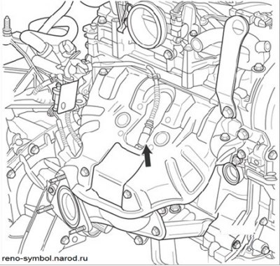
Figure 3.95. Upper Oxygen Sensor
To replace the upper sensor (see Figure 3.95) trace its wiring to the connector, disconnect the connector and unscrew the sensor from the exhaust manifold with a high head with a knob. Clean sensor threads, coat with non-stick compound, hand-tight, then torque-tight. The process of replacing the catalytic converter is described in subsection «Exhaust system».
Crankcase ventilation system
In case of intensive oiling of the air filter, it is necessary to check the connections, safety and internal cleanliness of the hoses and calibrated bushings. When inspecting and cleaning, mark the hoses so as not to mix up the hoses during installation.
Gasoline vapor recovery system
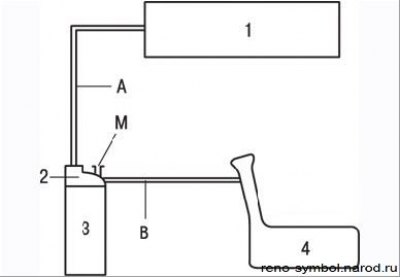
Figure 3.113. Scheme of the fuel vapor recovery system: 1 - intake manifold; 2 - solenoid valve of the fuel vapor recovery system; 3 - adsorber; 4 - fuel tank; M - hole for communication with the atmosphere; A, B - connecting hoses
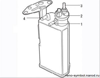
Figure 3.114. Adsorber: 1 - pipeline from the fuel tank; 2 - solenoid valve for adsorber purge; 3 - pipeline to the intake manifold; 4 - hole for communication with the atmosphere
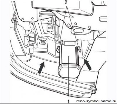
Figure 3.115. Removing the adsorber: 1 - adsorber; 2 - fastening bolts
When working, follow Figures 3.113, 3.114, 3.115.
Warm up the engine to operating temperature and stop it. Attach a voltmeter to the solenoid valve connector. Connect a vacuum gauge with a scale up to 1000 mbar to the hose between the adsorber and the solenoid valve.
Let the engine idle. The voltmeter should not show voltage, the vacuum gauge should not show vacuum.
If depression is registered, temporarily disconnect and blow from the remains of vapors of gasoline the hoses coming from the valve. If the voltmeter shows voltage at the valve, the wiring or the ECU is faulty.
Slightly increase the engine speed - voltage and vacuum should appear on the instruments. If there is no vacuum, the reason lies in the violation of the tightness of the hose connections or in the valve malfunction. The reason for the lack of voltage is a malfunction of the computer or wiring.
Removal and installation of an adsorber
Under the hood, disconnect the hose connecting the canister to the intake manifold. Engage the parking brake, raise the front of the vehicle and install jack stands. Remove the right front wheel and mudguard to access the canister mounted under the front bumper support.
Disconnect the hose leading to the tank from the adsorber. Turn away bolts of fastening and remove an adsorber from under a wing. Handle the adsorber carefully - it may contain fuel or its vapors.
Installation is carried out in the reverse order of removal. Install hoses correctly.
Removal and installation of the adsorber solenoid valve
The solenoid valve is mounted on top of the intake manifold.
Disconnect the connector and hoses from the valve. Remove the valve.
Installation is carried out in the reverse order of removal. Install hoses correctly.