
Removing the exhaust pipe and catalytic converter
Withdrawal:
- trace the wiring to the oxygen concentration sensor in the exhaust gases, disconnect the sensor connector and release the wiring from the fasteners;
- turn out bolts of fastening of a reception pipe to an arm on a transmission;
- unscrew the bolts and unscrew the nuts securing the exhaust pipe flange to the manifold, remove the gasket;
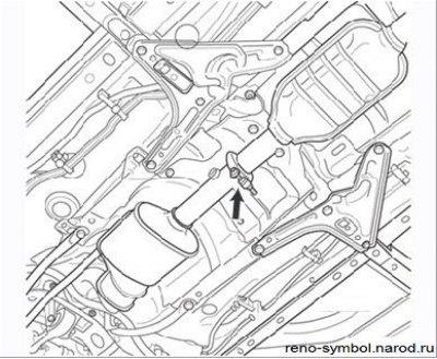
Figure 3.117. Connecting the downpipe and the rear of the exhaust system (the arrow points to the connecting collar)
- unscrew the nuts and remove the clamp (Figure 3.117);
- Remove the downpipe with catalytic converter from under the vehicle.
Attention! It is forbidden to strike the catalytic converter housing - this leads to its failure.
Installation
Installation is carried out in the reverse order of removal. Replace the 3-point flange gasket and exhaust pipe clamp. Tighten nuts of fastening of a reception pipe the demanded moment.
Note. A damaged heat shield must be replaced to prevent fire.
Resonator replacement
The back of the system is non-separable, i.e. there are no pipe connections from the resonator to the exhaust pipe, so if you need to replace any element, you should cut it out with a tool (e.g. scissors).
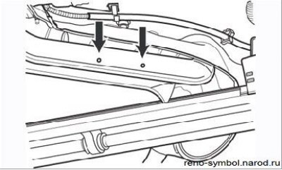
Figure 3.118. Marks on the exhaust pipe for cutting out the resonator
To cut the resonator, locate approximately the middle of the pipe between the resonator and the muffler. The cutout location is marked with two round marks on the side of the pipe, spaced 90 mm apart (Figure 3.118). You need to cut exactly in the middle between the marks.
Note. The cut should be as even as possible to get a good seal with the new pipe.
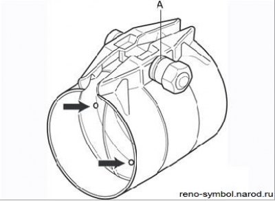
Figure 3.119. Coupling: A - a groove for the correct tightening of the nut; the arrows show the protrusions limiting the position of the connected pipes
After cutting off the pipe, remove the resonator from under the car. A coupling is used to subsequently connect the new resonator to the remaining part of the exhaust pipe (Figure 3.119).
To avoid leakage of exhaust gases, it is necessary to correctly install the coupling on both parts of the exhaust pipe. This means that the pipe must reach to the stop against the protrusions inside the coupling. The coupling should first be put on the already used part of the pipe, and then adjust the diameter of the coupling by slightly tightening it. Then the resonator tube should be inserted into the coupling.
Before installing the coupling on the pipe, mastic can be applied to the inner surface of the coupling to prevent leakage of exhaust gases.
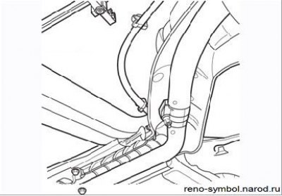
Figure 3.120. The location of the turnbuckle on the pipe
The coupling must be installed in such a way that the coupling bolt is located strictly vertically in order to avoid contact with the bottom of the body (Figure 3.120).
The coupling nut has a groove A (see Figure 3.120), which serves to determine the correct tightening torque. In the process of tightening, when this groove disappears, a characteristic click is heard. This means that the nut is tightened with the required torque of 25 Nm.
When installing, do the following:
- make sure that the pipeline of the exhaust system does not come into contact with the bottom of the body anywhere;
- make sure that all heat-reflecting shields of the system are present and securely fastened;
- make sure that both cutout zone marks are exactly aligned;
- check that the rubber brackets are not torn or cracked, replace them if necessary.
Attention! A previously installed clutch cannot be reused.