



Caution! Under normal operating conditions, the vent hole must be open.
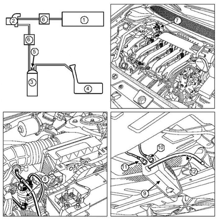
Fig. 2.284. Functional diagram and arrangement of elements of the toxicity reduction system: 1 – intake manifold; 2 – electromagnetic valve for purging the adsorber; 3 – adsorber; 4 – fuel tank; 5 – opening for communication with the atmosphere; 6 – check valve (only on F4R 776 engine); 7 – electromagnetic valve for purging the adsorber (K4M); 8 – Evaporative Emissions Blow-off Solenoid Valve (F4R); 9 – adsorber; 10 – pipeline for supplying gasoline vapors from the fuel tank; 11 – pipeline for supplying gasoline vapors to the intake manifold; 12 – communication tube with the adsorber atmosphere