



The described system includes a catalytic converter of exhaust gases, a crankcase ventilation system and a gasoline vapor recovery system.
Exhaust gas control is performed by a catalytic converter and two oxygen concentration sensors. These sensors provide feedback via the engine injection system ECU. One sensor is screwed into the upper part of the exhaust manifold, the other is located behind the catalytic converter. The ECU regulates the mixture composition, creating optimal operating conditions for the converter. The catalytic converter consists of a cylinder with a fine mesh covered with catalytic material, through which the exhaust gases pass. The catalyst ensures a high oxidation rate of harmful carbon oxides (CO), unburned hydrocarbons and soot, thereby reducing the emission of toxic products into the atmosphere.
The oxygen concentration sensor sends a voltage signal to the ECU, which changes depending on the oxygen concentration in the exhaust gases: low voltage corresponds to a low oxygen level, with a leaner mixture and an increase in the oxygen concentration in the exhaust gases, the voltage increases.
The voltage reaches its peak value at a stoichiometric mixture ratio of 14.7 parts (by weight) of air and 1 part of fuel. Around this value, the voltage coming to the ECU from the sensor varies widely, changing the width of the injector opening pulse.
The Crankcase Ventilation System reduces the release of unburned hydrocarbons from the crankcase into the atmosphere. The system is closed, gases and oil vapors are extracted from the crankcase and fed to the intake manifold through a wire mesh oil separator for afterburning during normal combustion in the cylinders.
In all engine operating modes, crankcase gases are removed under the influence of increased pressure in the crankcase.
To ensure proper operation of the system, the hoses and calibrated bushings must be cleaned periodically.
The fuel vapor recovery system minimizes the release of unburned fuel vapors into the atmosphere. The fuel tank communicates with the atmosphere through a carbon adsorber installed in the front right part of the engine compartment behind the bumper support. The adsorber captures fuel vapors from the tank when the car is parked and stores them until the engine is started and warmed up. The purge valve opens on command from the ECU, and the vapors enter the cylinders through the intake manifold, where they burn in the normal mode.
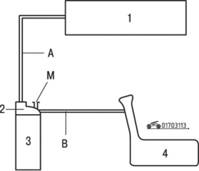
Fig. 3.113. Schematic diagram of the fuel vapor recovery system: 1 – intake manifold; 2 – fuel vapor recovery system electromagnetic valve; 3 – adsorber; 4 – fuel tank; M – opening for communication with the atmosphere; A, B – connecting hoses
The system operation diagram is shown in Fig. 3.113, the adsorber is shown in Fig. 3.114.
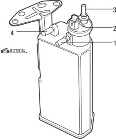
Fig. 3.114. Adsorber: 1 – pipeline from the fuel tank; 2 – electromagnetic valve for purging the adsorber; 3 – pipeline to the intake manifold; 4 – hole for communication with the atmosphere