



Contents: Parts and materials for repair 🠛 Instructions to be followed 🠛 Features of the one-piece exhaust…🠛
Parts and materials for repair
Parts that must be replaced:
- exhaust pipe coupling (if there is one),
- gasket or sealing ring connecting the catalytic converter or pre-catalytic converter to the rest of the exhaust manifold,
- exhaust pipe clamp or clamps (if they exist).
Materials:
- exhaust system sealant,
- surface cleaner,
- matting circles of gray color.
Instructions to be followed
Important Note: Catalytic converters contain ceramic fibers inside; they are enclosed in a closed container from which they cannot spill. It is prohibited to make holes or cut catalytic converters.
1. When removing and installing the catalytic converter or pre-catalytic converter, they must not be subjected to mechanical impacts that could lead to their destruction.
2. The exhaust system is made entirely of stainless steel.
3. Make sure that the flange connection of the catalytic converter or pre-catalytic converter to the rest of the exhaust pipe is completely sealed.
To do this:
- using grey matting wheels, clean the mating surfaces of the joint,
- degrease the mating surfaces of the joint with a surface cleaner and a clean cloth,
- be sure to replace the gasket or sealing ring of the connection.
Features of the one-piece exhaust manifold
Cutting a solid exhaust pipe
The exhaust pipes are made in one piece.
To replace individual parts of the exhaust pipe, it must be cut.
To do this you need:
- clearly mark the cutting area as explained below,
- use cutting tool correctly (Mot. 1199-01),
- install the exhaust pipe coupling correctly.
Marking the cutting area of the exhaust pipe
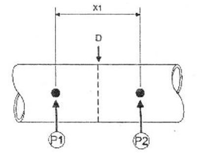
The cutting area is indicated by two marks located on the outlet pipe.
Example of cutting area
Before cutting the exhaust pipe, mark the middle (D) between the two marks (P1) and (P2).
The distance between the two marks on the exhaust pipe is (X1): 80 mm.
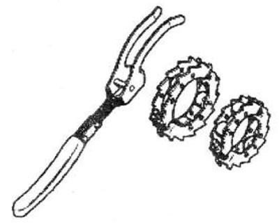
Using the Mot. 1199-01 tool
Install the fixture (Mot. 1199-01) (1) on the exhaust pipe.
 |
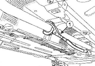 |
Tighten the two screws until the fixture contacts the pipe so that the cutter is lightly pressed against the pipe.
Rotate the cutter using the handle, pressing it against the pipe (as shown in the picture above).
As the operation progresses, tighten both fixture screws until the cut is complete.
Note: To avoid deformation of the pipe, do not tighten the screws of the fixture too much.
After cutting the pipe, use a file to remove any burrs from the portion of the exhaust pipe that will be reused on the vehicle.
Installing the exhaust pipe coupling
Attention! The old exhaust pipe coupling cannot be reused.
1 Bolt Exhaust Pipe Coupling
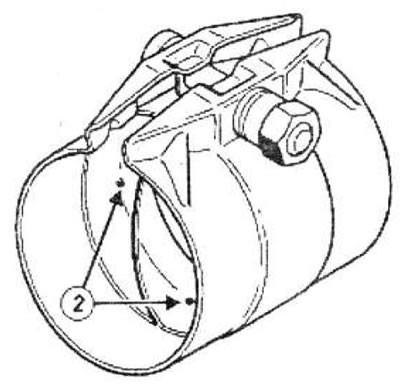
2 Bolt Exhaust Pipe Coupling
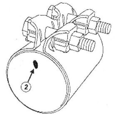
Place the coupling onto the exhaust pipe portion installed on the vehicle.
Adjust the outlet pipe until it contacts the projections (2) inside the repair coupling.
Lightly tighten the exhaust manifold coupling bolt or bolts (depending on the model).
Install the second part of the exhaust pipe onto the vehicle by inserting it into the exhaust pipe coupling.
Note: If necessary, use a hydraulic jack to lift and support heavy or large exhaust pipe components.
Insert the second section of the exhaust pipe until it contacts the protrusions inside the exhaust pipe coupling.
Check the alignment of the cutting area marks (3) (if they exist).
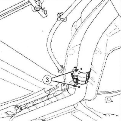
Orient the coupling so as to prevent its tie bolt or bolts from coming into contact with the heat shields.
Tighten to the specified torque:
- exhaust manifold coupling nut with one tightening bolt (25 Nm) (if there is one),
- exhaust manifold coupling nuts with two tie bolts (18 Nm) (if there is one).
Check and correct if necessary:
- no contact between the exhaust pipe and the heat shields under the body,
- the presence and reliability of fastening of all heat shields.
Note: A damaged heat shield must be replaced.
Start the engine.
Check for leaks and repair if necessary.
Note: If gas leaks from the exhaust pipe branch A with 1 clamp bolt, apply exhaust sealant to the branch.
If the leak cannot be fixed with sealant:
- remove and replace the used exhaust manifold coupling,
- check the condition of the exhaust pipes (condition of pipe surfaces, presence of burrs in the cutting area, deformation of pipes),
- reinstall the exhaust pipe coupling following the above instructions.