
Attention! Before doing any work on or near safety components, be sure to lock the airbag computer with a scan tool. In this case, all ignition circuits are blocked, and the airbag warning light on the instrument panel lights up with a constant light (with the ignition on).
Note. This operation does not require the use of a car lift.
Removing
Put the wheels of the car in position for driving in a straight line.
Disconnect the wires from the battery terminals, starting with the negative terminal.
Pic. 5.7. Removing the hatch cover to the lower casing
Detach the hatch cover to the lower casing (pic. 5.7).
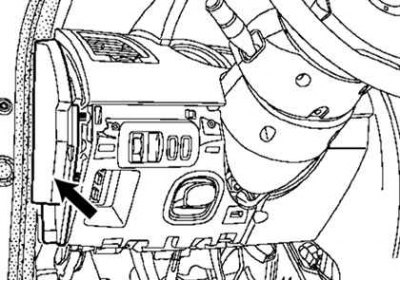
Pic. 5.8. Removing the side shield
Remove the side shield (pic. 5.8).
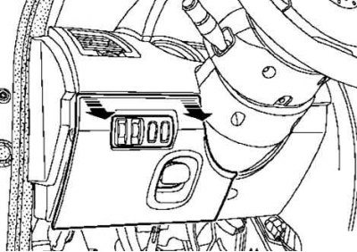
Pic. 5.9. Removing the bottom cover: 1 - fastening screws
Loosen the five screws securing the bottom cover and remove it (pic. 5.9).
Rotate the steering wheel half a turn to access the hole at the bottom of the steering wheel.
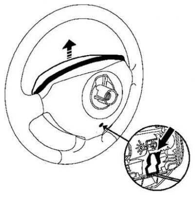
Pic. 5.10. Removing the airbag module
Insert a screwdriver into the hole, disconnect the clip shown by the arrow in Figure 5.10, and remove the airbag.
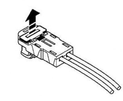
Pic. 5.11. Removing the airbag connector holder
Remove the airbag connector holder with a flat blade screwdriver (pic. 5.11).
Pic. 5.12. Removing the airbag
Remove connector and driver airbag (pic. 5.12).
Set the wheels to straight ahead.
Pic. 5.13. Removing the steering wheel: 1 - fastening bolt
Loosen the steering wheel bolt and remove it (pic. 5.13).
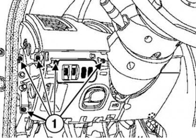
Pic. 5.14. Removing the upper and lower steering column covers: 1 - fastening screws
Remove the three lower screws and remove the upper and lower steering column covers (pic. 5.14).
Mark the position of the steering column switch block.
Make sure that the label on the contact disk is opposite the pointer.
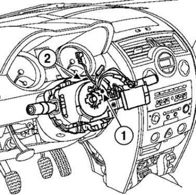
Pic. 5.15. Removing the steering column switch block: 1 - label; 2 - fastening screw
Remove the steering column switch (pic. 5.15).
Loosen the screw.
Disconnect the block from a steering column.
Disconnect:
- wire blocks (wiper switch, audio remote control, outdoor lighting switch, direction indicators and fog lights);
- block of wires from the contact disk.
Remove two screws.
Detach the two top clips.
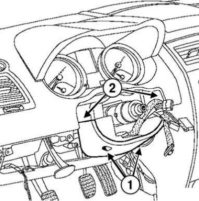
Pic. 5.16. Removing the second lower steering column cover: 1 - fastening screws; 2 - clamps
Remove the second lower stalk cover (pic. 5.16).
Partially detach the top of the instrument panel.
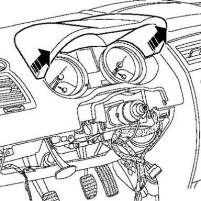
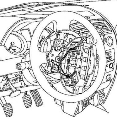
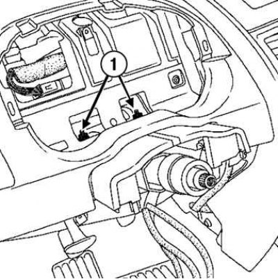
Pic. 5.17. Removing the top of the instrument panel
Disconnect the connector of the Carmi-nat navigation system (depending on equipment level) (pic. 5.17).
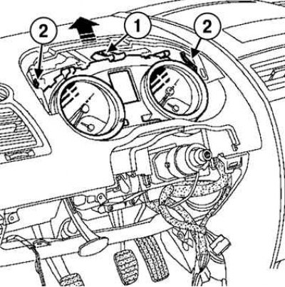
Pic. 5.18. Removing the instrument panel: 1 - screw; 2 - spring latches
Turn away the screw, wring out both spring latches and remove a panel of devices (pic. 5.18).
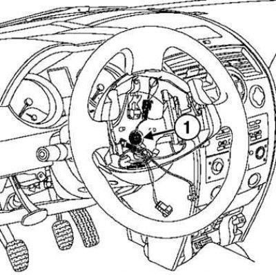
Pic. 5.19. Unscrewing the bolt of the steering shaft universal joint yoke: 1 - fastening bolt
Turn away a bolt of terminal connection of a plug of the universal joint of a steering shaft (pic. 5.19).
Disconnect the anti-theft device with a flat blade screwdriver.
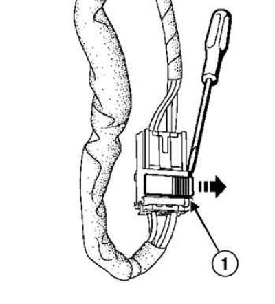
Pic. 5.20. Disconnecting the ignition lock connector: 1 - connector
Disconnect the ignition switch connector with a flat blade screwdriver (pic. 5.20).
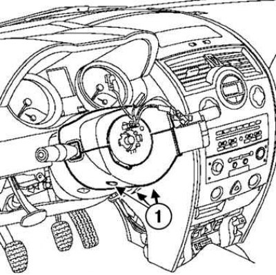
Pic. 5.21. Disconnecting the steering column mountings on the side of the instrument cluster: 1 - nuts
Unscrew the two nuts securing the steering column from the side of the instrument cluster (pic. 5.21).
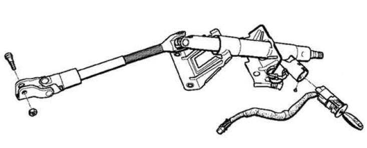
Pic. 5.22. Steering column
Remove the steering column (pic. 5.22).
Installation
Installation is made in an order, the return to removal.
Attention! The steering wheel must slide freely into the splines (slots have guide sections).
Attention! Be careful not to damage the splines of the orienting sections.
Attention! Be sure to replace the mounting bolt each time the steering wheel is removed.
Note. Be sure to replace the universal joint bolt and eccentric nut after each removal.
Note. The new steering column has an eccentric nut for the steering shaft universal joint yoke.
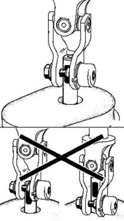
Pic. 5.23. Steering shaft universal joint bolt and eccentric nut installation
Observe the installation direction of the bolt and eccentric nut of the steering shaft universal joint yoke (pic. 5.23).
Tighten the eccentric nut and bolt.
Fix the terminal connection nut in the socket (hole on the yoke of the universal joint of the steering shaft).
Torque tighten:
- steering column nuts (21 Nm);
- Steering shaft universal joint yoke bolt (21 Nm).
Attach the wires to the battery terminals, starting with the positive terminal.
Carry out a complete check with the diagnostic tool.
Remove from the memory of the malfunctions that appeared as a result of the work performed with the diagnostic tool.