



Contents: Removal 🠛 Installation 🠛 Removal 🠛 Installation 🠛 Removal 🠛 Installation 🠛 Removal 🠛 Installation 🠛
Cars with F engines
Removal
- Disconnect the cable from the negative battery terminal.
- Disconnect all electrical connectors from the generator.
- Disconnect the connector from the knock sensor.
- Disconnect the connector from the ignition coils.
- Loosen the tension of the generator drive belt by unscrewing the tension roller mounting bolt (Fig. 15.3).
- Loosen the bolt (2, Fig. 15.3), nut and bolt (3) and remove the generator.
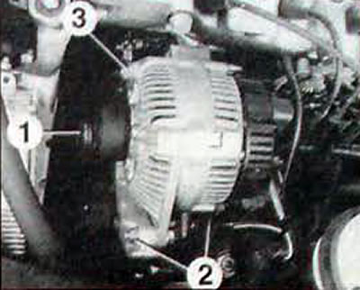
Fig. 15.3. Generator mounting elements on engine F: 1 - tension roller mounting bolt; 2 - generator mounting bolt; 3 - generator mounting nut and bolt
Installation
- The generator is installed in the reverse order of removal.
- Adjust the belt tension. Do not install the previously removed belt, replace it with a new one.
Cars with Z engines
Removal
- When removing the generator, first remove the windshield washer fluid reservoir and lower the air conditioning compressor.
- Place the vehicle on a two-post lift and disconnect the negative battery cable.
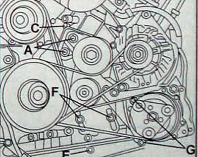
Fig. 15.4. Location of bolts for fastening the tension elements of the auxiliary equipment drive belts: A - generator drive belt tension roller mounting bolts; C - tension roller adjusting bolt; E - Water pump/air conditioning compressor drive belt adjusting bolt; F - bolts for fastening the tension roller of the water pump/air conditioning compressor drive belt; G - air conditioning compressor mounting bolts
- Disconnect the connector and remove the injection system control unit together with the bracket.
- Remove the right front wheel, mudguard and engine guards.
- Loosen the two bolts (A. Fig. 15 4) fastenings of the tension roller of the generator drive belt.
- Loosen the tension roller adjusting bolt (C) from above.
- Remove the upper alternator mounting nut. On the right side of the front cylinder head, remove the air conditioning hose bracket.
- Remove the alternator drive belt.
- Loosen the adjusting screw (E) of the air conditioning compressor drive belt.
- Loosen the adjusting screw lock nut and turn it out as far as possible.
- Loosen the two bolts (F) securing the air conditioning compressor drive belt tensioner roller.
- Remove the air conditioning compressor drive belt.
- Remove the oil filter.
- Remove the 4 air conditioning compressor mounting bolts.
- Remove the compressor from the bracket and move it to the side without disconnecting the hoses from it.
- Disconnect all electrical connectors from the generator.
- Unscrew the generator lower mount nut.
- Remove the windshield washer fluid reservoir.
- Disconnect the connector from the pump.
- Mark the location and disconnect the two tubes.
- Unscrew the lower tank mounting bolt.
- Lower the car.
- Unscrew the upper tank mounting bolt.
- Remove the reservoir with the pump from the car.
- Loosen the generator upper mounting bolt.
- Raise the vehicle and remove the alternator, while raising the tension roller as much as possible.
Installation
- The generator is installed in the reverse order of removal.
- To make it easier to tighten the generator upper mount nut, install the generator with two bolts pre-installed on it.
- Loosely install the air conditioning compressor onto the two bolts. Tighten the lower alternator mount nut and remove the compressor again to continue assembly
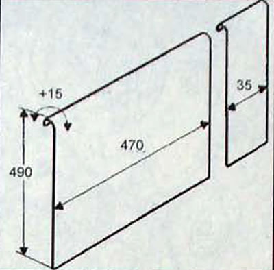
Fig. 15.5. Dimensions of the protective screen of the cooling system radiator
- Add engine oil if necessary.
- Adjust the belt tension. Do not install the previously removed belt, replace it with a new one.
Cars with G8T engines
Removal
- Place the vehicle on a two-post lift and disconnect the negative battery cable.
- Remove the right mudguard and the protective shields under the engine.
- Disconnect, without removing, the oil cooler from the engine cooling system radiator.
- Install a radiator protective screen made independently from steel or aluminum sheet (Fig. 15.5).
- Cars with air conditioning
- Install the Mot. 1370 lever by grasping the tension roller axle at the rear (Fig. 15.6).
- Lock the automatic tensioner by sliding it towards the rear of the vehicle and remove the belt.
- Install the lock Mot. 1376.
- Remove lever Mot. 1370 and install key Mot. 1368 (Fig. 15.7).
- Loosen the bolt and remove the eccentric adjusting roller.
- Disconnect the air conditioning hose from the power steering brace located between the engine and the power steering pump and remove the brace.
- Using pliers Mot. 453-01, pinch the power steering pump feed hose.
- Disconnect the supply hoses and high pressure hoses from the power steering pump.
- Remove the power steering pump.
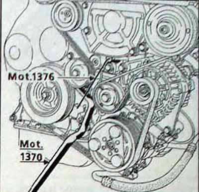
Fig. 15.6. Loosening the drive belt tension of the attachments on a G8T diesel engine with an air conditioning system
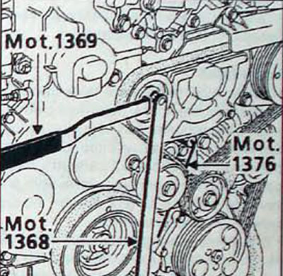
Fig. 15.7. Using special tools to remove the eccentric adjusting roller
Caution: Be sure to protect the generator from oil.
- Remove the three power steering pump bracket mounting bolts.
- Remove the power steering pump assembly with the bracket
- Disconnect all electrical connectors from the generator.
- Remove the upper and lower generator mounting bolts.
- Remove the alternator by sliding it upward through the space left by removing the power steering pump.
- Cars without air conditioning
- Loosen the tension of the alternator drive belt. To do this, use an internal Allen key to loosen the central bolt securing the tension roller by a quarter of a turn, then turn the roller counterclockwise (Fig. 15.8).
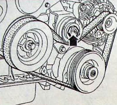
Fig. 15.8. Location of the central bolt for fastening the alternator drive belt tension roller
- Remove the accelerator cable.
- Disconnect all electrical connectors from the generator.
- Unscrew the two generator mounting bolts and remove the generator.
Installation
- The generator is installed in the reverse order of removal.
- On vehicles without air conditioning, use an Allen key to tighten the center tensioner pulley mounting bolt until it stops and the tensioner pulley gap is eliminated.
- Install a new belt and adjust its tension. Do not install the previously removed belt, replace it with a new one.
Cars with G9T engines
Removal
- Place the vehicle on a two-post lift.
- Disconnect the cable from the negative battery terminal.
- Disconnect the connectors from the generator and air conditioning compressor.
- Remove the right front wheel, the right wheel arch mudguard and the engine oil pan guard.
- Remove the front bumper, windshield washer reservoir and the pipe running from the heat exchanger to the throttle assembly.
- Loosen the belt tension by turning the tension roller axle clockwise with an open-end wrench and secure the roller with the device (Fig. 15.9).
- Remove the accessory drive belt.
- Remove the accessory drive belt idler pulley (fig. 15.10).
- Remove the four air conditioning compressor mounting bolts and leave the compressor suspended by the hoses (fig. 15.11).
- Loosen and remove the lower generator mounting bolt and loosen the upper bolt without removing it (fig. 15.12).
- On the lower right side of the vehicle, unscrew the vertically located bolt securing the reaction rod.
- Unscrew, without removing them, the fastenings of the preliminary catalytic converter of exhaust gases to the exhaust system.
- Remove the upper alternator mounting bolt by lifting the power unit towards the front of the vehicle, the bolt can be removed above the right side member and the alternator can be removed
Installation
- The generator is installed in the reverse order of removal.
- Install a new belt and adjust its tension. Do not install the previously removed belt, replace it with a new one.
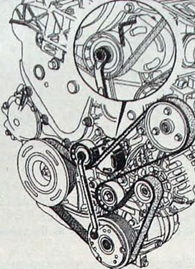
Fig. 15.9. Loosening the auxiliary drive belt tension
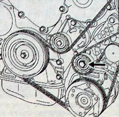
Fig. 15.10. Location of the auxiliary equipment drive belt idler roller
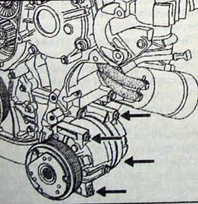
Fig. 15.11. Location of air conditioner compressor mounting bolts
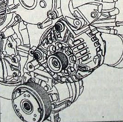
Fig. 15.12. Location of generator mounting bolts