



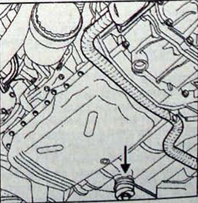
Fig. 15.13. Location of the engine mount thrust rod
The generator disassembly and assembly operations do not present any particular difficulties. After disassembling the generator, the following must be checked:
- condition of the brushes, degree of their wear, position and their pressure on the collector;
- the condition of the collector, which must be cleaned with a piece of cloth soaked in essential oil or trichloroethylene and polished with glass paper;
- condition of bearings that do not require any maintenance. The grease incorporated into the bearings is designed for the entire service life;
- the condition of the rotor and stator, which should not have any damage or burn marks;
- avoid using ungrounded electric soldering irons, as if their insulation is damaged they will cause breakdown of the generator rectifier diodes;
- immediately after cleaning the parts (especially windings) they should be dried with a stream of compressed air.
Note: During generator checks, the supply voltage of the measuring device must not exceed 14 V
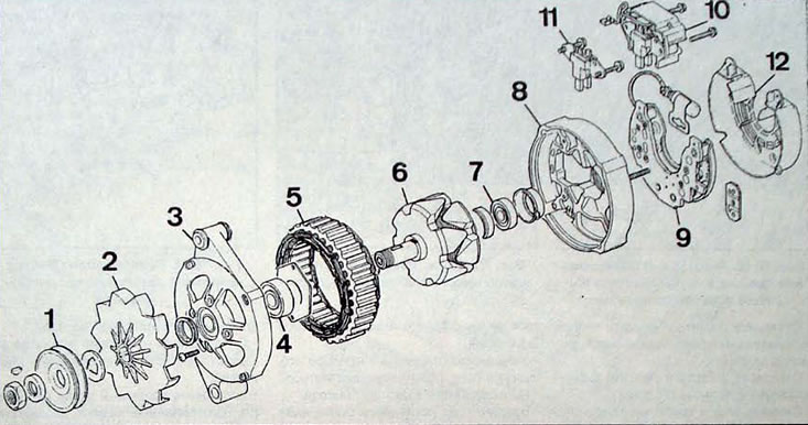
Fig. 15.14. Generator: 1 - pulley; 2 - fan; 3 - front cover; 4 - bearing; 5 - stator; 6 - rotor; 7 - bearing; 8 - back cover; 9 - rectifier; 10 - voltage regulator; 11 - brushes; 12 - protective cover