
The electronic module converts the low voltage into the high voltage required for the ignition system to operate. The function of the mentioned components is described below, which is also relevant for a 4-cylinder fuel-injected engine.
On the side of the module with the carburetor installed there is a plate (see illustration 1.1), which shows the ignition timing adjustment curve. The numbers behind the mark «RE» are very important, since they determine, among other things, the moment of ignition.
1.1 Location of the rating plate with setting data on the control unit
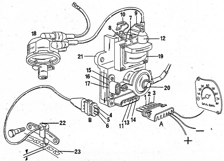
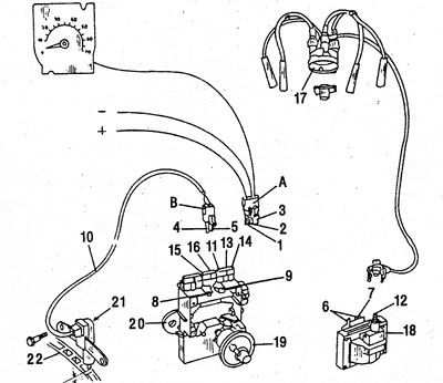
Figure 1.2 shows the electronic ignition components, along with connections, on a carbureted engine. Illustration 1.3 shows the system components on a fuel injected engine. The main difference is in the connection method.
1.2 Components of the electronic ignition system with a carburetor engine 1. To the positive terminal; 2. To mass; 3. To the tachometer; 4. The sensor of inclusion of the moment of ignition; 5. The sensor of inclusion of the moment of ignition; 6. Screen; 7. Positive terminal of the ignition coil; 8. Negative terminal of the ignition coil; 9. Positive ignition coil cable; 10. Negative ignition coil cable; 11. Positive input of the electronic module; 12. Secondary connection; 13. Mass of the electronic module; 14. Tachometer output; 15. Ignition moment sensor pulse; 16. Ignition moment sensor pulse; 17. Screen; 18. Cover separating the breaker from the ignition distributor; 19. Ignition coil; 20. Vacuum ignition timing; 21. Electronic module; 22. Ignition moment sensor; 23. Flywheel

1.3 Components of the electronic ignition system 1. To the positive terminal; 2. To mass; 3. To the tachometer; 4. The sensor of inclusion of the moment of ignition; 5. The sensor of inclusion of the moment of ignition; 6. Positive terminal of the ignition coil; 7. Negative terminal of the ignition coil; 8. Positive terminal of the ignition coil; 9. Negative terminal of the ignition coil; 10. Connecting wire; 11. Positive input of the electronic module; 12. High voltage secondary output; 13. Mass of the module; 14. Tachometer output; 15. Ignition moment sensor pulse to; 16. Ignition moment sensor pulse; 17. Cover separating the breaker from the ignition distributor; 18. High voltage ignition coil; 19. Vacuum ignition timing; 20. Electronic module; 21. Ignition moment sensor; 22. Flywheel
The flywheel crown has 44 teeth that are evenly distributed around the perimeter, however, two teeth are omitted at 180°intervals, so the TDC sensor can accurately indicate 90°BTDC and BDC.
The TDC sensor detects both dead center positions and engine speed and sets the ignition timing to match engine speed as closely as possible. Illustration 1.4 shows the details described.
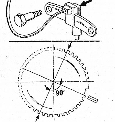
1.4 The ignition timing sensor in the flywheel housing in the upper figure, and the location of the flywheel teeth in the lower figure
Vacuum Ignition Timing Acts as a normal regulator in a conventional ignition system and adjusts ignition timing according to engine load (only for carbureted engine).
Fuel injection vehicles have an intake manifold absolute pressure sensor that sends an electrical impulse to the electronic module to set the injection timing.
The ignition coil functions separately from the module and can also be replaced separately. On a carbureted engine, the ignition coil is installed in the ignition control device, and on a fuel injected engine, it is installed separately.
The fuel injection engine ignition control computer determines the ignition timing according to engine speed and low engine pressure. Setting the ignition timing is only possible on carbureted engines.
If any of the electrical connections need to be disconnected, refer to illustrations 1.2 and 1.3 for subsequent connection. Remember that a short circuit can damage the electronic components of the system.
Ignition system - V6 engine
The ignition system of the V6 engine is based on the ignition system of the 4-cylinder engine. The following is a brief description:
- A full stroke of a four-stroke engine takes two revolutions of the crankshaft (720°), i.e. in a six-cylinder engine, an ideal ignition pattern is obtained when the ignition of the combustible mixture occurs every 120°revolution of the crankshaft. The connecting rod journals of the crankshaft of the Espacc engine move 30°, i.e. TDC is set every 90°. One of the cylinders in each row is always at TDC.
- How to find the first cylinder? As you can see in illustration 1.5, cylinders No. 1,2 and 3 are located in the left row (cylinder bank A), and in the right row - cylinders No. 4, 5 and 6 (cylinder bank B).
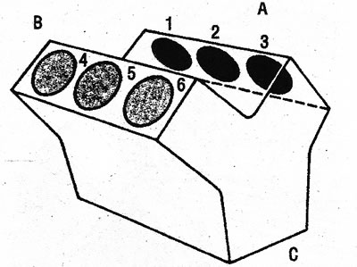
1.5 Arrangement of cylinders in rows (A) And (IN) on a V6 engine. Engine turned sideways (WITH). Cylinder #1 is on the flywheel side
These directions are determined, provided that you look at the engine from the side «WITH». As you can see in the picture, cylinders #1 and #4 are on the flywheel side. If you turn the crankshaft so that the piston of the first cylinder is set to TDC (both valves of this cylinder are closed) and from this position turn the crankshaft further, the remaining pistons will be installed at TDC in the indicated sequence: 6-3-5-2-4, i.e. ignition order: 1-6-3-5-2-4.
The contacts in the ignition distributor are located at 60° (total 360°), so that each revolution of the crankshaft reaches the next cylinder.
To check if the piston is at TDC, look through the hole in the flywheel housing and remove the cylinder head covers 4,5 and 6. The mark on the flywheel must be aligned with the mark «0» on the clutch housing, as shown in illustration 1.6. The valves of the fifth cylinder should switch, i.e. one valve closes and the other opens. Cylinders operating in «couples»: 1 and 5.2 and 6.3 and 4. The rest of the cylinders can be set to TDC in the same way.
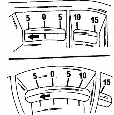
1.6 This is how the mark on the flywheel should be located in relation to the mark «ABOUT» on the clutch housing. Top for manual transmission models, bottom for automatic transmission