
Steering elements
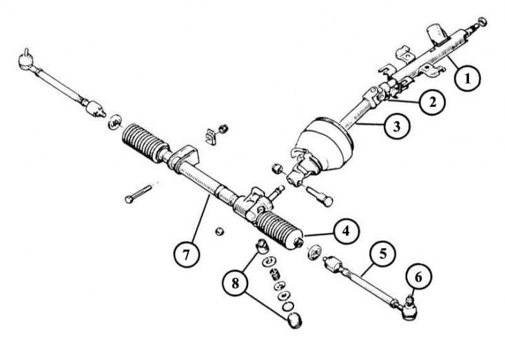
1 - pipe-shell with an upper steering shaft and a mount for the ignition lock-switch and anti-theft device; 2 - cardan joint; 3 - lower steering shaft; 4 - steering sealing cuff; 5 - thrust of the steering trapezoid; 6 - the tip of the transverse steering rod; 7 - gear rack housing; 8 - a cracker with a thrust ring, a pressure spring and a plug for adjusting the small steering gear.
Steering swivel parts
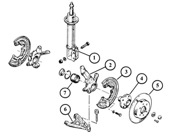
1 - stand with shock absorber assembly; 2 - steering swivel support; 3 - brake disc reflector; 4 - wheel hub; 5 - brake disc; 6 - transverse suspension arm; 7 - wheel bearing.
The tie rod ends are screwed on individually. Thus, in case of damage, there is no need to completely change the entire tie rod.
1. Raise the machine, secure the front and remove the wheel.
2. Loosen the self-locking nut from the tie rod end on the steering pivot steering arm.
3. Using a puller, press the tie rod end down out of the steering arm, and then unscrew the nut.
4. Loosen the jam nut on the end of the tie rod while holding the tie rod hex on the transmission side with a wrench.
5. Unscrew the tip from the tie rod, while remembering the exact number of revolutions to facilitate subsequent assembly.
6. Tighten the tie rod end nut to 35 N.m.
Note. Recommendation: to protect the tie rod ends from premature wear due to damage to the sealing collar, they must be wrapped with a clean cloth immediately after they have been pressed from the steering pivot; it is also necessary to protect the control arm ball head.
Replacement of sealing cuffs of a steering drive
1. Remove the tie rod ends. When unscrewing, write down the exact number of revolutions in order to be able to set the tips to their previous position during subsequent assembly - otherwise the alignment will be violated!
2. Loosen and remove both o-ring tie-down straps. Replace first assembly tie-downs with threaded tie-downs.
3. Remove the sealing collar.
4. Before installation clean draft of a steering trapezoid and slightly grease it.
5. Slide the sealing collar along the steering link rod and at the same time make sure that it sits correctly in the grooves of the steering link rod and the rack housing and is not twisted. Otherwise, the cuff will be damaged and will not be able to provide the necessary tightness.
6. Secure the sealing collar with a tie strap. Install the outer collar of the sealing collar only after the machine has been lowered and the correct alignment has been checked.
7. Install the steering link rod ends and tighten them with a new self-locking nut to 35 N.m.
8. Check camber and steering wheel position and adjust if necessary.
Removing the steering pivot
1. Loosen the wheel bolts.
2. Loosen the wheel hub nut (head SW 30).
3. Raise the machine, secure and remove the wheel.
4. Remove the disc brake caliper and hang it on a wire.
5. If there is ABS, then disassemble the speed sensor and wire bracket from the shock absorber strut.
6. Turn off a bolt of a brake disk and remove it from a nave of a wheel. You may need to use an impact screwdriver.
7. Remove the brake disc deflector.
8. Remove the tie rod end.
9. Wring out the spherical joint of the cross-section lever from a steering rotary support. To do this, unscrew the fixing bolt.
10. Remove the steering pivot from the shock absorber.
11. Turn off a nut of a nave of a wheel and remove it by means of a puller from a steering rotary support. If there is ABS, then disassemble the speed sensor in advance.
12. Pull off a steering rotary support from a forward semiaxle or wring out it by means of a stripper from a power shaft.
13. Hang the axle shaft with a wire.
14. Installation is carried out in the reverse order of removal.
15. Put the wheel hub on the wedge engagement of the drive shaft and press the hub nut. Pre-lubricate the driveshaft spline with Loctite Scelbloc to secure the spline in the steering pivot.
Removing the front wheel bearing
The sectional drawing shows the front wheel bearing in the steering swivel bearing
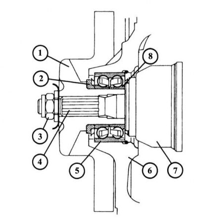
1 - wheel hub; 2 - thrust ring; 3 - wheel hub nut; 4 - spline connection of the output end of the drive shaft; 5 - outer rotating ring of the bearing; 6 - steering swivel support; 7 - drive shaft hinge; 8 - inner rotating ring of the bearing.
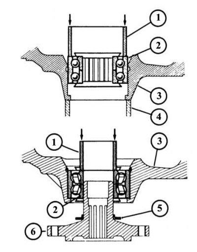
Pictured here (top drawing), how a full wheel bearing is pressed in first (2) through a pipe of suitable diameter (1) to the stop on the steering swivel support (3). In this case, the outer side rests on a suitable ring support (4). The inner plastic ring should not be removed yet, as it holds the inner rotating ring.
After installing the spacer ring (5) (bottom figure) on the wheel hub (6) both inner bearing races must be pressed in (after removing the plastic sleeve) assembled with a steering swivel support using a pipe of a suitable diameter (1) on the wheel hub. The corresponding pipe diameter values are indicated in the text earlier.
Since only a Renault workshop has all the necessary tools to remove the bearing, it is best to carry it out there. The front wheel bearings run in precisely calibrated rotating rings. Bearings, rotating rings, hub and steering knuckle have tight tolerances. Therefore, the bearings are not adjusted. Due to tight tolerances, precise and technically correct assembly is essential.
The outer ring of the bearing is pressed into the steering swivel bearing, and the inner rotating ring of the bearing is pressed onto the wheel hub. In no case should you hit the new bearing with a hammer when installing it, as this can lead to bearing failure after a few thousand kilometers. If one bearing is damaged, both rotating bearings and O-rings must be replaced at once.
1. Remove the steering pivot.
2. Clamp the wheel hub in a vise with protective cheeks.
3. With puller (e.g. Renault FACOM U53G+53E attachment with Rou protection clutch. IS-01) remove the bearing inner race from the hub.
4. Clamp the steering swivel bearing in a vise and remove the bearing thrust ring from the wheel hub hole with pliers.
5. Press the outer bearing race with one of the inner bearing races out of the hub bore. To do this, it is not necessary to remove the bearing housing and seals.
6. When installing, remove both outer plastic guards of the new bearing and insert the bearing together with the guard of the inner ring into the hole in the wheel hub of the steering pivot.
7. According to wheel hub bore diameter (63 or 71 mm) fit a short pipe of the appropriate diameter to the outer ring of the wheel bearing and press the bearing in until it stops. In this case, in no case rest against the inner ring!
8. Remove the inner safety plastic sleeve.
9. Insert the wheel bearing thrust washer.
10. Lubricate the sealing lips of the bearing with an appropriate lubricant.
11. Push the thrust ring onto the wheel hub.
12. Install the steering pivot onto the wheel hub.
13. Take a piece of pipe (outer diameter 45 or 48 mm respectively, inner diameter 39 or 43 mm respectively) with a diameter that exactly matches the diameter of the inner ring of the bearing, and press the steering swivel bearing against the wheel hub until it stops.
Note. Recommendation: If the Renault 19 is equipped with ABS, make sure that the impulse wheel is not damaged during work, otherwise the ABS may fail.