



Contents: Removal 🠛 Installation 🠛
| Tightening torques | |
| Nut for fastening the silent block of the left support of the pendulum suspension | 62 Nm |
| Exhaust manifold flange mounting bolts | 21 Nm |
| Upper mounting bolts of the front suspension subframe connecting rods | 21 Nm |
| Bolts for fastening the pin of the upper ball joint of the stabilizer bar | 37 Nm |
| Bolt for fastening the "mass" busbar to the gearbox | 21 Nm |
| Bolt securing low pressure power steering line to front suspension subframe | 21 Nm |
| Bolts securing the power steering line to the gearbox support | 21 Nm |
| Bolts securing the power steering line to the gearbox | 21 Nm |
| Bolt securing power steering line to cylinder block | 21 Nm |
Removal
Place the vehicle on a two-post lift.
Models with air conditioning
Drain the refrigerant from the refrigeration circuit using a refrigerant charging station.
All models
Remove:
- top engine cover,
- air intake pipe,
- air filter housing, battery,
- battery tray,
- Injection system ECU.
Loosen the bolt (1) securing the engine wiring harness to the battery bracket.
Disconnect the engine wiring harness from the retainer at point (2).
Loosen the bolt securing the ground busbar (3) on the battery bracket.
Disconnect the connector (4) of the pre- and post-heating unit.
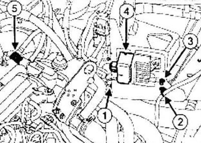
Disconnect the check valve (5) from the vacuum pump.
Remove the fuse and relay box cover.
Remove the side protective shield (6) of the fuse and relay box.
Disconnect the engine wire harness connector from the front vehicle wire harness (7).
Remove the engine wiring harness fuses and relays (8) from their holders in the engine compartment fuse/relay box.
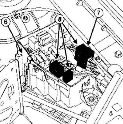
Place the wiring harness with fuses and relays on the engine.
Remove:
- front wheels,
- engine oil pan protection mounting bolts,
- engine oil pan protection,
- front bumper,
- front wheel arch guards.
Drain:
- motor oil if necessary,
- gearbox oil,
- coolant.
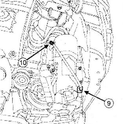
Disconnect the connector (9) of the water presence sensor on the fuel filter.
Disconnect the water presence sensor connector on the fuel filter bracket at point (10).
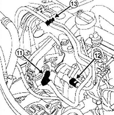
Disconnect:
- fuel supply line (1),
- fuel drain line (12).
Caution: To prevent corrosion or damage, protect areas where fuel spills may cause damage.
Insert plugs into the fuel supply line holes.
Disconnect the pipes at (13).
Disconnect the air lines from the air cooler.
Disconnect:
- harness of the electromagnetic valve of regulation of the boost pressure at point (14),
- electromagnetic valve for regulating the boost pressure (15) from the bracket.
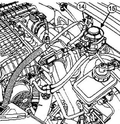
Disconnect:
- air duct (16) on the exhaust gas recirculation unit,
- air duct between turbocharger and cooler at point (17).
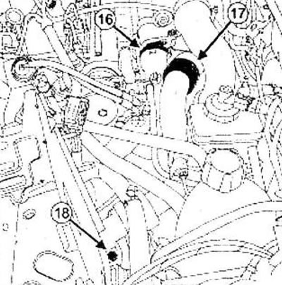
Remove:
- the fastening nut (18) of the air duct on the gearbox,
- air ducts from the air cooler.
Disconnect:
- low pressure hose of the power steering system on the power steering pump using (Mot. 1448) and drain the working fluid from the circuit,
- high pressure line on the power steering pump,
- the wiring harness from the pressure relay in the power steering system.
Models with heater
Remove:
- low pressure line of the power steering system (19) on the reservoir using (Mot. 1448),
- power steering pump reservoir (20), power steering high pressure line fastening bolt to the cylinder block.
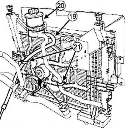
Disconnect the power steering lines on the engine cooling fan bracket at point (21).
Disconnect the wiring harness (22) from the engine cooling system electric fan.
Models with air conditioning
Loosen the bolt securing the high pressure power steering line to the cylinder block.
Disconnect the wire connectors (23) from the engine cooling system electric fan.
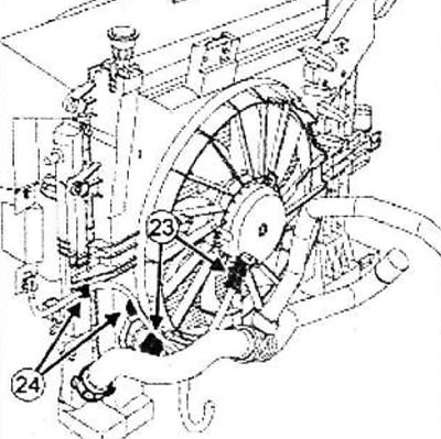
Disconnect the engine cooling fan wiring harness at point (24).
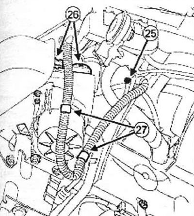
Unscrew the bolt securing the ground busbar (25) to the body.
Disconnect the connectors (26) of the electric pump.
Disconnect the electric pump wiring harness at point (27).
All models
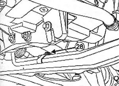
Loosen the bolt (28) securing the low pressure power steering line to the holder on the front suspension subframe.
Remove:
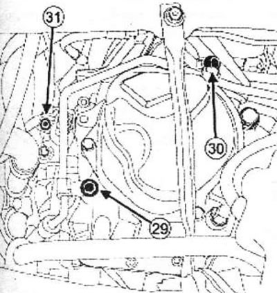
- power steering high pressure pipe mounting bolt
- (29) on the gearbox,
- power steering high pressure pipe mounting bolt
- (30) on the gearbox support,
- mounting bolt (31) of the "mass" busbar on the gearbox.
Models with air conditioning
Loosen the bolts securing the pipeline fittings to the compressor.
Disconnect the compressor lines.
Note: Be sure to plug the pipe openings to prevent moisture from entering the system.
Seal the pipe openings.
Disconnect the refrigerant pressure sensor connector.
All models
Loosen the expansion tank mounting nuts.
Move the expansion tank to the side.
Move aside the coolant hose clamp (32) on the thermostat housing using the tool (Mot. 1448).
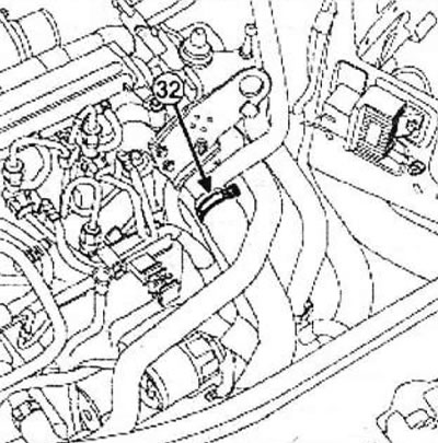
Disconnect the coolant hose at the thermostat housing.
Move aside the coolant hose clamps (33) on the heater radiator using the tool (Mot. 1448).
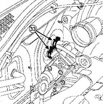
Disconnect the inlet and outlet hoses from the heater radiator.
Remove the cooling system hoses from the holders.
Remove:
- steering gear mounting bolts,
- steering gear heat shield,
- steering gear mounting bolts on the front suspension subframe.
Secure the steering gear to the body.
Remove:
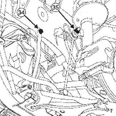
- bolts (34) of the upper fastening of the connecting rods of the front suspension subframe,
- upper mounting bolts for the ball joint pins of the anti-roll bar struts (35).
Remove:
- right front wheel drive shaft,
- left front wheel drive shaft.
Route the low pressure power steering line over the transmission cover.
Disconnect:
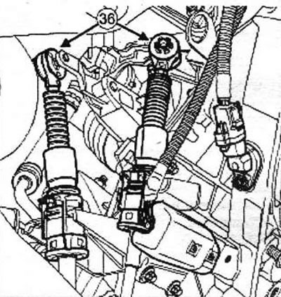
- gear selection and shift cables from the gearbox at points (36) using a screwdriver,
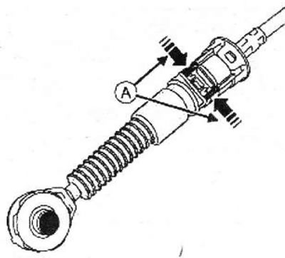
- selector and gear shift cables from the casing stoppers by pressing at point (A).
 |
 |
Move the control cable away from the gearbox.
Attention! Do not pull the lock. Any erroneous action requires replacement of the pipeline.
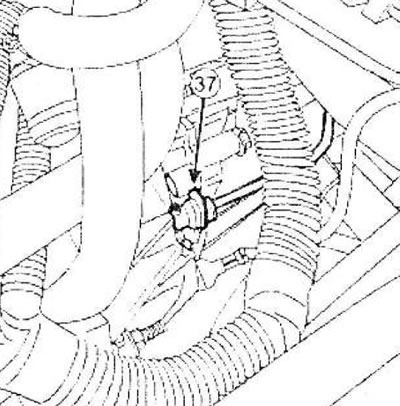
Disconnect the clutch hydraulic line from the slave cylinder by pressing the retainer (37).
Drain the brake fluid into a container.
Seal the pipe openings.
Remove the lower reaction rod.
Remove:
- bolts (38) for fastening the exhaust pipe flange.
- exhaust manifold sealing ring.
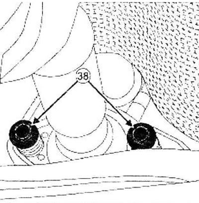
Move the exhaust pipe to the side.
Note: Move the exhaust pipe back.
Remove the front suspension subframe.
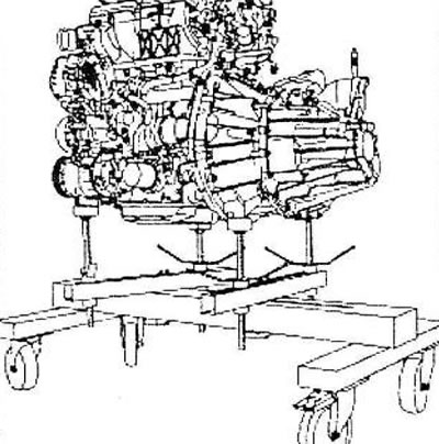
Note: Correctly install the tool (Mot. 1390) on the multifunctional bracket in area (39).
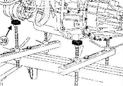
Install (Mot. 1390) under the engine and gearbox assembly.
Remove the right swingarm support.
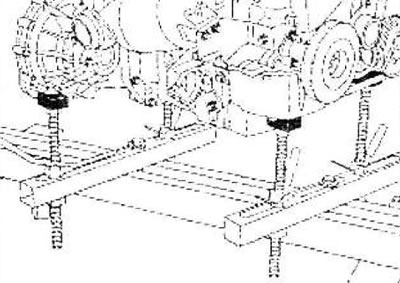
Loosen the fastening nut (40) of the silent block of the left pendulum suspension support.
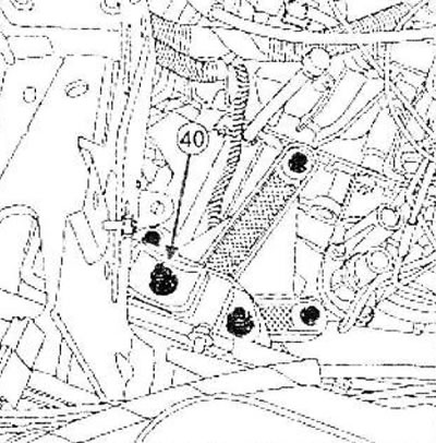
Use a bronze drift to knock out the gearbox mounting stud to separate the engine and gearbox assembly from the body.
Raise the vehicle and remove the engine and gearbox assembly.
Note: Make sure nothing interferes with the removal of the engine and transmission assembly from the body.
Remove the engine assembly with the gearbox.
Installation
Parts that must be replaced: ring between the exhaust manifold and the catalytic converter.
Install the engine assembly with the gearbox.
Tighten the nut securing the silent block of the left pendulum suspension support.
Tighten the nut securing the silent block of the left pendulum suspension support to the required torque (62 Nm).
Install the right pendulum support.
Remove the tool (Mot 1390) from the engine/gearbox assembly.
Installation is carried out in the reverse order of removal.
Tighten to the specified torque:
- exhaust pipe flange mounting bolts (21 Nm),
- upper mounting bolts for the front suspension subframe connecting rods (21 Nm),
- bolts for fastening the pin of the upper ball joint of the anti-roll bar (37 Nm),
- bolt for fastening the "mass" busbar to the gearbox (21 Nm),
- bolt for fastening the low pressure power steering line to the front suspension subframe (21 Nm),
- power steering pipe mounting bolts on gearbox support (21 Nm), power steering pipe mounting bolts on gearbox (21 Nm),
- power steering pipeline mounting bolt on the cylinder block (21 Nm).
Perform:
- fill the engine with oil, fill the gearbox with oil,
- filling the engine cooling system and removing air from it,
- remove air from the clutch hydraulic system.
Models with air conditioning
Charge the refrigeration circuit with refrigerant using the refrigerant charging station.
All models
Fill the power steering system with working fluid.
First, stop the engine and bleed the power steering system by turning the steering wheel from the left extreme position to the right.
Start the engine and bleed the power steering system by turning the steering wheel from one extreme position to the other.
Bring the oil level in the power steering pump reservoir to normal.
Check for fuel leaks.