



Contents: Removal 🠛 Installation 🠛
Note: New cylinder head and valve cover gaskets will be required during installation.
Removal
1. Apply the handbrake, then jack up the front of the car and place it on axle stands. Remove the front right wheel.
2. Disconnect the negative cable from the battery.
3. To facilitate access, remove the hood as described in Section 11.
4. Drain the cooling system as described in Section 1.
5. Remove the toothed drive belt as described in Chapter 7.
6. Remove the air cleaner assembly as described in Section 4C.
7. Remove the intake manifold as described in Section 4C.
8. Loosen the clamps and disconnect the three cooling system hoses from the thermostat housing (see illustration).
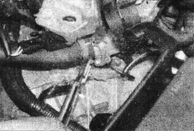
11.8. Disconnect the cooling system hoses from the thermostat housing.
9. Disconnect the ignition control module wiring, then remove the four mounting bolts and remove the module from the valve cover (see illustration).
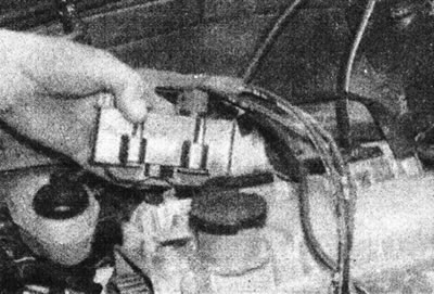
11.9. Remove the ignition control module.
10. Release the wiring harness from the clips at the rear of the valve cover (see illustration).
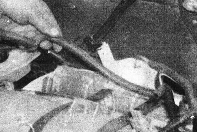
11.10. Release the wiring harness from the clips on the rear of the valve cover.
11. Loosen the clamps and disconnect the heater hoses from the water pump and from the connector on the transmission side of the valve cover (see illustrations).
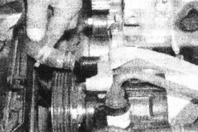
11.11a. Disconnect the cooling system hoses from the water pump...
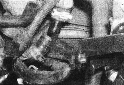
11.11b....and from the connector on the valve cover on the transmission side.
12. Unscrew the mounting bolts and lift the valve cover and gasket together with the heater hose. Please note that one of the valve cover mounting bolts is hidden under a rubber plug in the cover on the camshaft sprocket side (see illustrations).
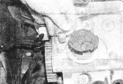
11.12a. Remove the rubber plug...
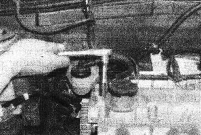
11.12b....to gain access to one of the valve cover mounting bolts.
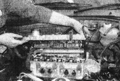
11.12s. Remove the valve cover.
13. Disconnect the exhaust outlet pipe from the manifold as described in Section 4C.
14. Disconnect the connectors from the coolant temperature sensor, coolant temperature gauge sensor, and the charcoal canister valve coil (see illustration).
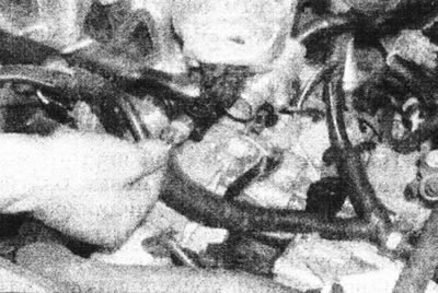
11.14. Disconnect the wiring from the coil of the carbon canister valve.
15. Working in reverse order of tightening (see illustration 11.28), gradually loosen the cylinder head mounting bolts. Remove the bolts (see illustrations).
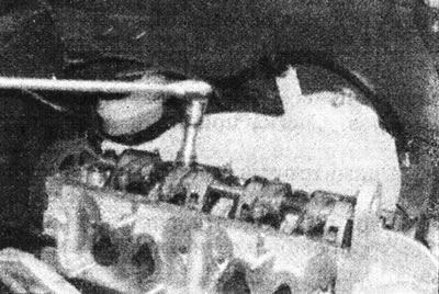
11.15a. Gradually unscrew...
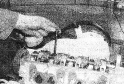
11 15b....and remove the cylinder head mounting bolts.
16. Release the head from the cylinder block and mounting pins by rocking it from side to side. Do not use a screwdriver for this.
17. Carefully lift the head from the block (see illustration).
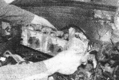
11.17. Lift the head from the cylinder block.
Remove the gasket, it needs to be replaced.
18. If required, the camshaft can be removed as described in Chapter 10, and the cylinder head can be disassembled as described in Part F of this Section.
Installation
19. Clean the mating surfaces of the head and cylinder block/crankcase. Use a scraper to remove any remaining gasket material and carbon deposits, and clean the tops of the pistons. Work especially carefully to avoid scratching the aluminum surface of the cylinder head. Also, make sure that no dirt has entered the oil passages and cooling passages - this is especially important for the lubrication circuit, as carbon particles can block the oil supply to the camshaft, rocker shaft, rocker arms or crankshaft bearings. Using masking tape and paper, seal all holes in the cylinder block. Also clean the piston heads.
20. Inspect the mating surfaces of the cylinder block/crankcase and head for deep scratches and other damage.
21. If the cylinder head is suspected of being warped, check it using the edge of a straightedge. If necessary, see Part F of this Section.
22. Wipe the mating surfaces of the head and cylinder block/crankcase. Make sure the two dowel pins are in place on the edges of the cylinder block/crankcase.
23. Make sure that piston #1 remains at TDC position when the marks on the camshaft and crankshaft sprockets are correctly aligned (see Chapter 3). Do not rotate the camshaft and crankshaft until the timing belt is installed.
24. Place the new head gasket on the cylinder block, sliding it over the pins so that the word "TOP" is on the intake manifold side (see illustration).
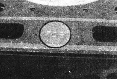
11.24. The "TOP" mark on the head gasket must be on the intake manifold side.
25. Lower the cylinder head into the working position, placing it on the pins.
26. Apply a thin coat of clean engine oil to the threads of the new cylinder head bolts.
27. Carefully insert the bolts into the holes and screw them in by hand until they stop.
28. Tighten the cylinder head bolts in the sequence shown to the torque specified in the Specifications (see illustration).
View the original on the specified resource RenaultBook
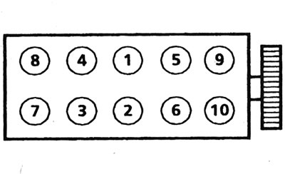
11.28. Sequence of tightening the cylinder head bolts.
The first three stages are for pre-compressing the gasket, while the rest are the main tightening procedure for the bolts.
29. Connect the wiring to the coolant temperature sensor, the coolant temperature gauge sensor and the charcoal canister purge valve coil.
30. Connect the exhaust outlet pipe to the manifold as described in Section 4C.
31. Install the valve cover using a new gasket and tighten the mounting bolts in a spiral pattern (from the center outward), see tightening order. in the Specifications.
32. Connect the heater hose to the water pump and the pipe on the cover, and secure it with clamps.
33. Secure the wiring harness to the valve cover with staples.
34. Install the ignition control module and tighten the mounting bolts, then connect the electrical wiring to it.
35. Connect the cooling system hoses to the thermostat housing and secure them with clamps.
36. Install the intake manifold as described in Section 4C.
37. Install the air filter assembly.
38. Install the toothed drive belt as described in Chapter 7.
39. Fill the cooling system as described in Section 1.
40. Install the hood as described in Section 11.
41. Install the wheel (tighten the bolts to the torque specified in the Specifications) and lower the car to the ground, then connect the negative cable to the battery.