
Attention! To prevent damage to the contact disc under the steering wheel, observe the following instructions:
- before disconnecting the steering shaft from the steering mechanism, be sure to block the steering wheel with a special device with the wheels set to the position of movement in a straight line, and the steering wheel must remain locked during the entire time of work;
- if there is any doubt about the correct centering of the contact plate, remove the steering wheel and center the contact plate.
Removing
Place the car on a two post lift.
Remove the engine top covers.
Disconnect the wires from the battery terminals, starting with the negative terminal.
Remove:
- air intake pipe;
- battery;
- battery shelf;
- injection computer with bracket;
- intake air duct;
- wiring harness attachment.
Remove the ball end of the multifunction switch cable with a tool and remove the cable.
Disconnect the wiring harness from the speed sensor, the wiring harness, releasing the movable part of the connector and unscrew the mounting bolts of the modular connector bracket.
Attention! Protect the connector by placing it in a waterproof plastic bag.
Remove the engine speed sensor.
Clamp the hoses with clamps.
Disconnect the hoses from the cooler.
Remove the wiring harness from the transmission.
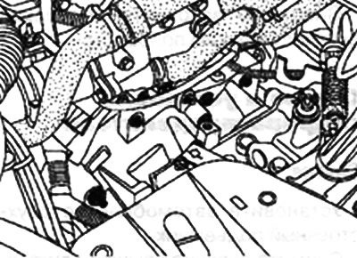
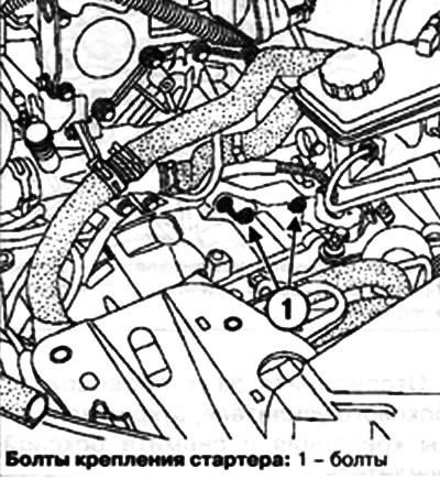
Remove the two starter mounting bolts and remove the engine undertray.
Drain the gearbox oil.
Remove wheels and fenders.
Disconnect the wires from the ABS sensors and the wires from the xenon headlight range control sensors (if they are installed).
Note. The xenon headlight range sensor is located on the left control arm.
Work performed on the left side of the vehicle
Loosen the hub nut using the tool (Rou. 604-01).
Remove the tie rod end ball joint using the tool (Tav. 476).
Remove the ball joint of the anti-roll bar using the tool (Tav. 476).
Remove the ball joint of the suspension arm.
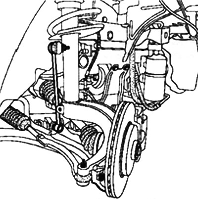
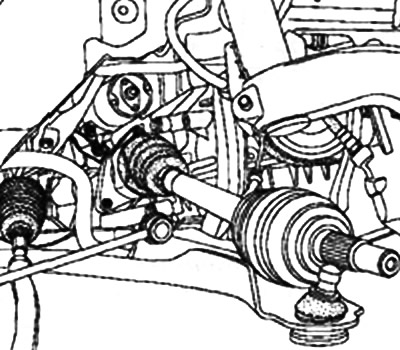
Disconnect the wheel drive shaft from the steering knuckle.
Remove the left front wheel drive shaft.
Remove the transmission ECU harness holder and side booster.
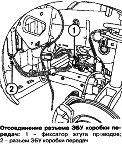
Open the transmission ECU harness lock and disconnect the transmission ECU connector.
Work carried out on the right side of the vehicle
Loosen the hub nut using the tool (Rou. 604-01).
Remove the tie rod end ball joint using the tool (Tav. 476).
Remove the ball joint of the anti-roll bar using the tool (Tav. 476).
Remove the ball joint of the suspension arm.
Remove the intermediate support flange.
Disconnect the drive shaft from the steering knuckle.
Remove the right front wheel drive shaft.
Secure the engine cooling radiator/condenser assembly to the top cross member with twine.
Remove the side reinforcement.
Remove the lower radiator cross member.
K4M engine
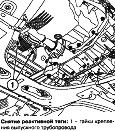
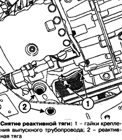
Loosen the exhaust manifold nuts and remove the tie rod.
F4R engine
Loosen the exhaust manifold nuts and remove the tie rod.
Remove the strut mounting the manifold to the bottom of the engine.
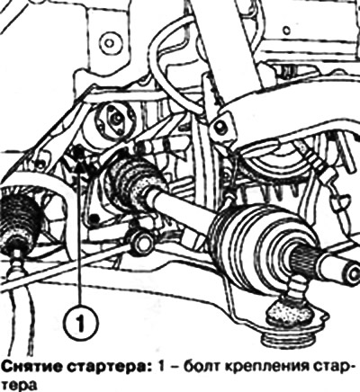
Loosen the mounting bolt and remove the starter.
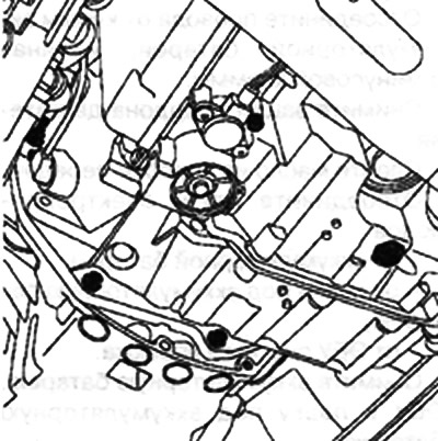
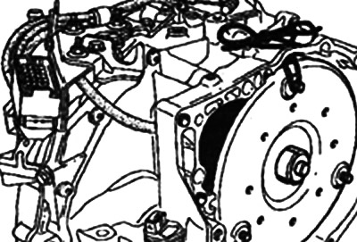
Loosen the three torque converter mounting nuts.
Note. Access to the torque converter fastening nuts opens after the starter is removed. Turn the crankshaft clockwise to access the three nuts connecting the drive plate to the torque converter.
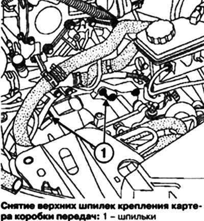
Remove the upper studs securing the gearbox housing to the engine block.
Secure the hood with straps.
Remove the gearbox support pad.
Place a hydraulic jack under the gearbox.
Remove the lower bolts securing the gearbox to the engine block.
Remove the transmission studs.
Remove the automatic transmission.
Secure the torque converter with a string to prevent it from moving.
Installation
Attention! Do not re-use torque converter and drive plate mounting nuts, be sure to replace them with new ones.
Check for mounting bushings.
Installation is made in an order, the return to removal.
When installing an automatic transmission on the engine, make sure that the input shaft of the gearbox and the torque converter are aligned exactly.
Torque tighten:
- wheel bolts (110 Nm);
- brake caliper guide bolts (7 Nm);
- nut of fastening of a finger of a ball joint of a tip of steering draft (37 Nm);
- nut of fastening of a finger of a spherical support of the suspension arm (62 Nm);
- tie rod to subframe bolts (105 Nm);
- gearbox and starter mounting bolts to the engine (44 Nm);
- gearbox pendulum nut (62 Nm);
- nut of fastening of a finger of a ball joint of a tip of steering draft (62 Nm);
- torque converter fastening nut on the drive plate (37 Nm);
- modular jack bracket bolts (20 Nm);
- bolts of fastening of the gauge of frequency of rotation of a cranked shaft of the engine (10 Nm);
- bolts for fastening jet thrust to the K4M engine (105 Nm);
- jet thrust bolts to the F4R engine (180 Nm);
- nut for fastening the pendulum support to the pillow (180 Nm).
Fill the oil in the automatic transmission and check its level.
8 In the event of an oil change, reset the adaptive correction parameters using the command: RZ 005 «Resetting bootstrap parameters» and reset the oil life counter in the automatic transmission computer by issuing command: CF074 «Recording the date of oil change in the gearbox».
After executing command RZ005, be sure to drive with repeated upshifts and downshifts to memorize new settings.