
Warning: Work on the system only if you have experience with the injection system. People with a pacemaker are not allowed to access the electronic injection system and the associated ignition system. Keep clean when disassembling the system.
The following figures show some components of the injection system of a 4-cylinder engine (see illustrations 10.1-10.4).
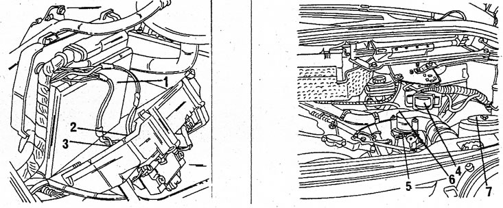
10.1 Position of the electronic module (1), both fuel pump relays (2) and injection systems (3) on models J636/J637. On earlier models, the module is located on the center console. The fuel pump and injection relays are located next to the left fog lamp. The remaining components indicated by numbers will be listed below
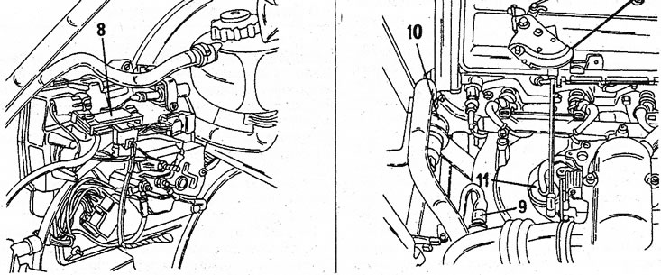
10.2 Location of some parts on models J636 and J637. Numerical designations are given in the text
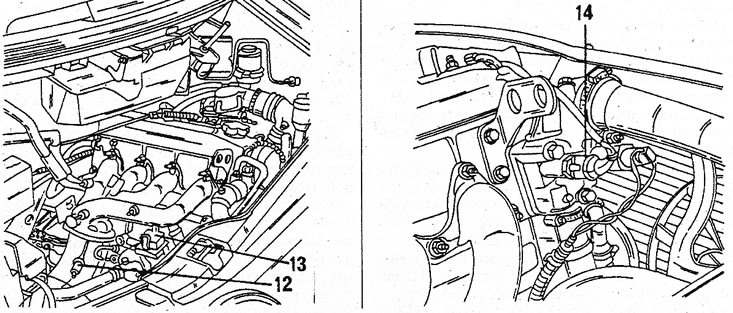
10.3 Lambda sensor location (12), sockets of the central plug for connection of the diagnostic stand (13) and coolant temperature sensor (14)
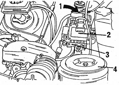
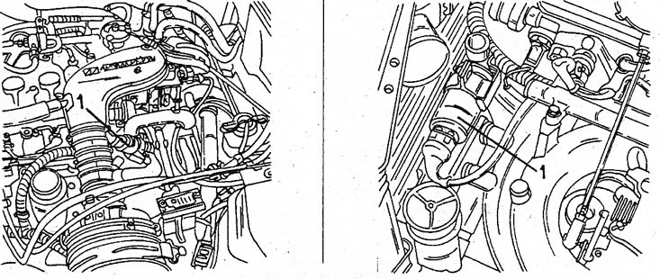
10.4 Adjusting bolt (1) CO content is behind the ignition module (2) on earlier models. Also shown is an absolute pressure sensor (3) and air filter (4)
Illustration 9.1 shows the position of most of the components in a V6 engine. Parts not shown for the 4-cylinder engine are:
- 2) fuel pump relay,
- 3) injection relay,
- 4) ignition module,
- 5) throttle body,
- 6) full load switch,
- 7) air filter,
- 8) absolute pressure sensor,
- 9) intake air temperature sensor,
- 10) idle speed control valve,
- 11) fuel pressure regulator,
- 12) socket of the central plug for connection of the diagnostic stand.
Most components require a room-specific tester to check, so repair only involves the replacement of damaged parts.
Idle speed and CO content cannot be adjusted on later models, which, on the contrary, is typical for earlier models J116 and J117. On these models, to adjust the CO content, a potentiometer is installed behind the ignition module and is closed with a cap. Figure 10.4 shows the location of the mentioned components.
The CO content cannot be adjusted automatically, but if you feel a very high CO concentration, first of all remember when the engine oil was last changed. For a possible adjustment, pull out the potentiometer, remove the plug from the hole and turn the screw that has opened with a screwdriver.
The idle speed cannot be adjusted on any of the fuel injected engines.
The intake air temperature sensor is installed in the air intake system and is located in a rubber tube with a spring clip.
coolant temperature sensor (4 cylinder engine (see illustration 10.3) must be removed when the engine is cold. Close the screw hole immediately as coolant may leak out. To get to the sensor on the V6 engine, remove the heater matrix, throttle body and intake manifold.
The MAP sensor fitted to later Espace models is located inside on the right fender under the plastic cover. On early models, the sensor is mounted on the bottom surface of the part (2), as shown in illustration 10.4 (where it is connected by a small hose). To replace, use a screwdriver to pry out the plug and hose.
The idle speed control valve is located in the location shown in illustration 10.5. To remove the valve, disconnect the electrical connectors, hoses and safety clip. On early models, the valve may be on the right side of the large air hose (hose between control valve and bypass). The arrow on the bottom of the valve indicates the direction of air flow.
10.5 Idle speed control valve (1). Right - 4-cylinder engine (later model), left - V6 engine