



Depending on the vehicle configuration, there may be several options for installing and routing auxiliary drive belts.
The stable operation of the engine largely depends on the condition of the drive belts of auxiliary units.
Check the condition of the drive belts in the following order:
- raise the front of the car and place it on stands;
- remove the engine compartment protective tray and the protective cover from under the right wing;
- using a portable lamp, inspect the belts for cracks, delamination, swelling, and excessive wear. During the inspection, turn the crankshaft pulley bolt with a suitable wrench or head with a ratchet. The unit pulleys should not have cracks, burrs, bends, or corrosion. Abrasions on the side surface of the belt indicate that the pulley axes are misaligned.
If any damage is detected, the belt must be replaced.
The belt tension is checked with a special device. Its reading for the generator drive belt should be (101±6) units and for the power steering pump drive belt (106±6) units.
If you don't have the above mentioned device, you can check the belt tension by pressing it with your thumb and determining the degree of its deflection with a ruler. The "thumb" rule states that if the distance between the pulley centers is from 180 to 280 mm, then the deflection should be 6 mm; if the distance between the pulley centers is 300–400 mm, then the deflection should be 13 mm.
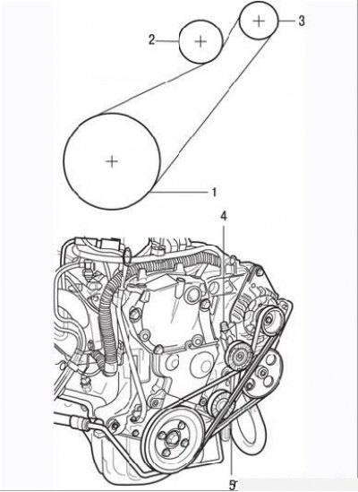
Figure 2.30. Auxiliary unit drive with tension roller: 1 – crankshaft pulley; 2 – tension roller; 3 – generator pulley; 4 – tension roller adjustment device; 5 – power steering pump drive belt; above is the generator drive diagram
Replacing the belt with tension roller:
- loosen the tension roller bracket mounting bolt to the engine (Figure 2.30);
- loosen the lock nut and back off the tension roller adjusting bolt just enough to allow the belt to be removed from the pulleys;
- install the new belt, carefully placing it in the grooves of the pulleys;
- adjust the belt tension as described above.
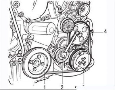
Figure 2.31. Auxiliary unit drive with spring-loaded roller: 1 – crankshaft pulley; 2 – spring loaded roller; 3 – air conditioning compressor pump pulley; 4 – power steering pump pulley
If a spring-loaded roller is used to tension the belt (Figure 2.31), then to loosen the belt, turn the roller clockwise using a suitable key and remove the belt from the pulleys.