Very often, a car owner has to deal with increased fuel consumption, loss of power, and sometimes even a complete failure of the car to move. Most often, this is caused by a malfunction of the fuel injectors due to the use of fuel of inadequate quality. And it does not matter whether this is caused by the driver's desire to save money on cheaper fuel or dishonesty of gas station employees. One way or another, the problem of the need to replace the injectors arises. The simplest (and undoubtedly the most correct) the way out in this case is to contact the nearest specialized service station. However, if the car owner believes that he is able to cope with the problem on his own, certainly saving some money, the following tips are provided to help him, which will either help the car enthusiast avoid mistakes in the process of work, or convince him to timely abandon the useless undertaking.
First of all, it is necessary to clearly understand that the replacement process itself (described in the relevant chapter of this Manual) should be performed only with certain skills, since it may contain certain dangers both for health and for human life - the fuel pressure in some injection systems of modern engines can reach 250 atm, therefore any carelessness can have fatal consequences.
The second, no less important point is that even in the case of a successful replacement of the fuel injector, there is a risk of getting as a result an injector with a spray of much worse quality than it was before the replacement, even under the condition of the highest quality of the replaced parts. What can we say about cases of using low-quality or defective injectors. It is in order to avoid such situations that it is necessary to use special diagnostic stands available at service stations. or, at least, the simplest device, which will be discussed below.
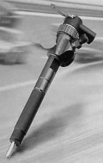
First, it is necessary to understand the structure of a diesel injector and understand the processes occurring in it. All injectors, with rare exceptions, are fundamentally similar, and the processes occurring in them are similar. The structure of a fuel injector is shown in the figure.
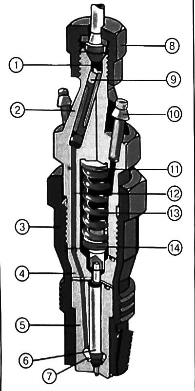
1. Inlet chamber. 2. Injector body. 3. Nozzle nut. 4. Spacer. 5. Nozzle. 6. Nozzle needle. 7. Nozzle cavity. 8. Union nut for connection to the high-pressure pipeline. 9. Filter. 10. Drainage system nipple. 11. Injection pressure regulation gasket. 12. High-pressure channel. 13. Spring. 14. Pressure pin.
The principle of operation of the fuel injector is as follows: fuel from the high-pressure pump (HPFP) enters the nozzle nipple, and from there through the system of channels (12) into the cavity of the atomizer (7). Further movement of fuel is blocked by the atomizer needle (6), pressed by the spring (13). Meanwhile. The HPFP continues to pump fuel, raising its pressure to a value capable of overcoming the force of the spring and lifting the atomizer needle above the seat. At the same time, fuel is injected into the cylinder, as a result of which the pressure drops again and the needle sits on the seat, cutting off the fuel supply and locking the system. With continued injection of fuel, the process is repeated. The main condition of operation in this case is that after the end of the injection, the system must close, otherwise, in the next stroke, fuel will be supplied not when the pressure in the system rises to the specified value, but at the moment the pump begins to supply fuel. The result will be rough engine operation, loss of power and failure of the fuel injector due to combustion products entering the unsealed system.
Knowing the operating principle of the injector, you can figure out what can interfere with the normal locking of the system with outwardly serviceable parts. Most often, this is due to the occurrence of lateral forces pressing the needle to the sprayer body. To combat such forces, there is a pressure pin (14) located in the spacer (4). The pin relieves the needle from the possible impact of a deformed spring, however, if there is some wear on it, the pin itself can cause lateral force. Therefore, when replacing fuel injectors, you need to be prepared for the fact that the sprayer will also start to "pour", which will require repeated overhaul of the injector with turning over the spring or replacing it or the pusher. In some cases, it may even be necessary to replace the fuel injector body.
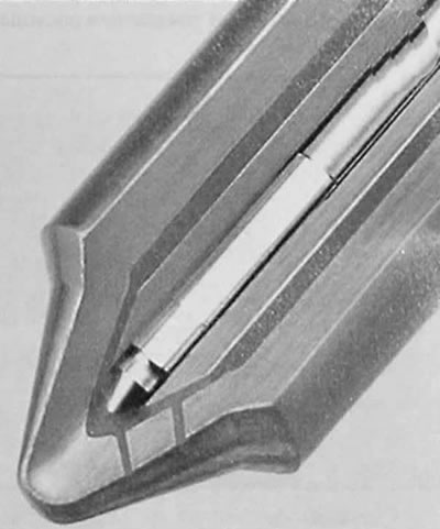
Since the needle in the sprayer is not sealed by anything, some fuel leaks between the needle and the body of the sprayer and gets into the cavity where the spring (13) is located. If the fuel is not removed from this cavity, the sprayer needle may lose its ability to move and the sprayer will be "locked". A drainage system (10) is used to remove leaked fuel.
The opening pressure of the needle is adjusted by adjusting linings (11), and the entire structure is tightened by a union nut (4).
There are no sealing elements in the injector, and the tightness is ensured exclusively by precision machining of the mating surfaces. As a result, the main requirement for working with fuel injectors is sterile cleanliness. Immediately after unscrewing the high-pressure pipeline from the injector, it is necessary to close the injector nipple with a clean and tight cap, since the slightest debris that gets into the injector nipple during testing on the stand will be driven inside by the fuel and can jam the spray needle. The injector cavity must always, either before testing and adjustment or after, be absolutely protected from any dust, not to mention larger particles. In addition, any dirt when removing the injector can get into the channel and then damage the thread or break the seat seal.
It is advisable to remove high-pressure pipelines in a package together with ties (if the engine design allows it), so there are fewer reasons to puzzle over how it all stood. If it is impossible to remove the pipelines as a package, it is necessary to mark the first cylinder nipple on the pump, and also mark the pipelines themselves in the order in which they stood.
After removing the injectors, it is necessary to check their performance, to make sure that the supposed cause of the engine malfunction is correct. The criteria for checking are as follows:
- When fuel is supplied, the injector must open under a given pressure.
- Fuel leakage from the spray nozzle is not allowed until the injector opens.
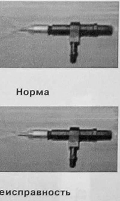
- When spraying fuel, drops and jets are not allowed.
- The spray pattern must be smooth, without deviations, and correspond to the direction of the hole (or holes) in a spray bottle.
After the fuel supply is stopped, the pressure in the injector should be maintained for some time (strictly speaking, the rate of fall of this pressure must be controlled).
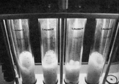
The amount of fuel sprayed by the injectors of the different engine cylinders must be the same.
It is obvious that the fuel injector in the third measuring cylinder delivers less fuel than the other injectors.
It is also common to talk about the characteristic sound of the injectors, but the sound is not an objective parameter for evaluating the injectors. This parameter cannot be ignored, but it should not be made the main one either.
Of course, the best way to check the performance of injectors is on a special stand. Design (and accordingly the cost) such a stand can be very diverse, which will undoubtedly affect the accuracy of diagnostics and ease of use. At service stations, stands with electronic control can be used that cost several thousand dollars, however, if the car owner is determined to diagnose the injectors on his own, it is recommended to make the simplest stand on his own
To do this, you will need to make a tee pipe, one end of which will be connected to one of the high-pressure fittings of the high-pressure fuel pump, the other to the fuel injector, and on the third end you need to attach a pressure gauge with a scale of 200-300 atm
A measuring vessel (ceiling glass) must be placed under the nozzle sprayer.
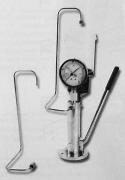
By turning the engine with the starter, you need to make the injector start to "shoot", after which, leaving the ignition on, turn the engine crankshaft manually, reading the pressure gauge readings (the process is tedious, but quite acceptable in the absence of other options).
In the overwhelming majority of modern injectors, the opening pressure is adjusted by selecting the thickness of the spacer washer between the spring and the body. Specialized workshops have sets of these washers to solve any adjustment problems. For car enthusiasts, it should be borne in mind that washers exist in different diameters (for various injector bodies), and are available with or without a hole. Washers with a hole can always be used instead of washers without a hole, but the reverse replacement is not allowed. It is also not allowed to use washers of the wrong diameter.
Typically, injectors are designed in such a way that increasing the thickness of the washer by 0.1 mm leads to an increase in injection pressure by 10 atmospheres (10 kg/cm³ or 980 kPa). Very often, when repairing injectors, it is seen that during previous interventions, the injection pressure was adjusted using pieces of razor blades placed under the spring. This method of adjustment is completely unacceptable. Firstly, having a lining of an uncontrolled shape creates uncertainty in the spring support and thus its non-uniform development, which provokes the occurrence of lateral force. In addition, there is a risk of chipping a piece of the blade, which will lead to complete failure of the injector. The use of metal foil is also unacceptable, since gaskets made of soft material are completely short-lived. Therefore, the only high-quality solution to the problem should be recognized as the use of new adjusting washers of the calculated thickness.
Flushing and cleaning fuel injectors at home is categorically not recommended due to the futility of the undertaking.
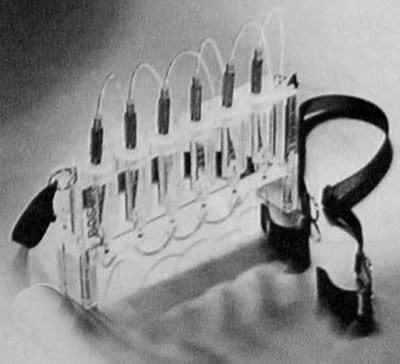
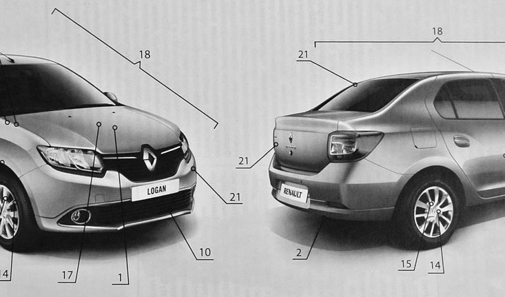
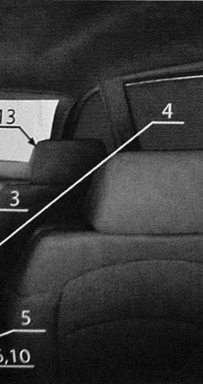
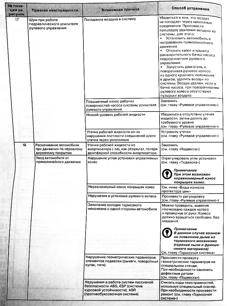
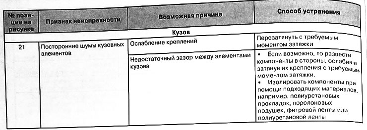
The illustrations provided will make it easier to identify a particular malfunction. Having noticed any deviations from the norm on your car (extraneous noises, knocks, leaks, signs of uneven wear, controllability problems, etc.) localize the location of the malfunction, compare it with the drawing and refer to the table at the appropriate link. If you cannot determine the exact source of extraneous noise, you must do this at least approximately. Then, using the illustrations and table, identify the specific malfunction.
The illustration and table below show the most common sources of noise, but similar symptoms may occur in other areas of the vehicle.
If it is not possible to determine the location of the fault from the drawing, then it is necessary to try to identify the cause according to the main categories and points given in the table.
Note:
In the figure the following positions indicate:
- 13 — Front suspension shock absorbers
- 20 — Pedal assembly
- 6, 10—Rear final drive gearbox
Table of causes of malfunctions in the car



[Article reprinted from the website: RenaultBook]