



Note: New cylinder head and valve cover gaskets will be required during installation.
Removal
1. Disconnect both cables from the battery (always start with the negative).
2. Drain the cooling system, including the cylinder block, as described in Section 1. The drain plug in the block is located on the crankshaft pulley side, below the water pump.
3. Drain the engine oil as described in Section 1.
4. Remove the air cleaner assembly as described in Section 4A.
5. Disconnect the high tension wires from the spark plugs, release the distributor cap retaining clips or screws, and remove the cover and wiring.
6. Disconnect the wire from the coolant temperature sensor on the water pump (see illustration).
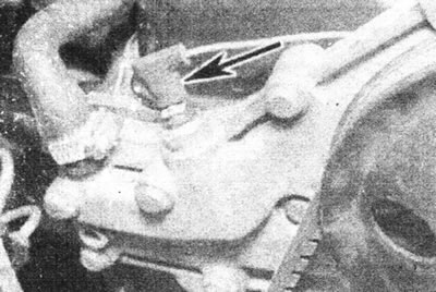
6.6. Disconnect the coolant temperature gauge sensor wire. liquids (marked with an arrow).
7. Loosen the generator mounting bolt and adjusting lever, push the generator toward the engine, and remove the drive belt from the pulleys. Remove the bolt securing the alternator adjustment lever to the water pump and move the alternator away from the engine (see illustrations).
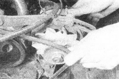
6.7a. Loosen the generator fasteners and remove the drive belt from the pulleys.
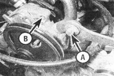
6.7b. Loosen the bolt (A) and disconnect the generator adjustment lever from the pump (B).
8. Loosen the clamps and disconnect the two heater hoses from the water pump. Also remove the bracket from the valve cover.
9. Loosen the clamp and disconnect the upper radiator hose from the water pump.
10. Disconnect the throttle cable, choke cable and vacuum line from the carburetor as described in Section 4A.
11. Disconnect the brake booster hose from the intake manifold.
12. Unscrew the nut and washer on the intake manifold and on the cylinder block, and remove the heat-insulating shield (where available).
13. Disconnect the fuel inlet hose and crankcase ventilation hose from the carburetor.
14. Disconnect the distributor wiring.
15. Remove the bolt and loosen the wiring harness retaining clip on the side of the cylinder head (see illustration).
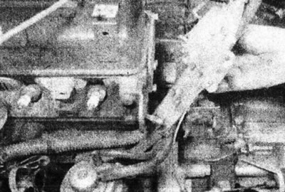
6.15. Remove the wiring retainer block.
16. Remove the two bolts and springs securing the front of the exhaust system to the exhaust manifold.
17. Unscrew the nuts and remove the valve cover together with the gasket from the cylinder head (see illustration).
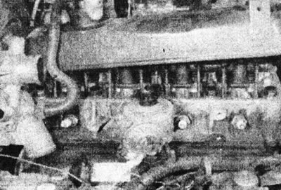
6.17. Unscrew the three nuts and remove the valve cover.
18. Gradually loosen the two bolts and two nuts securing the rocker arm axle supports to the cylinder head. Lift the rocker arm shaft assembly up off the two studs (see illustration).
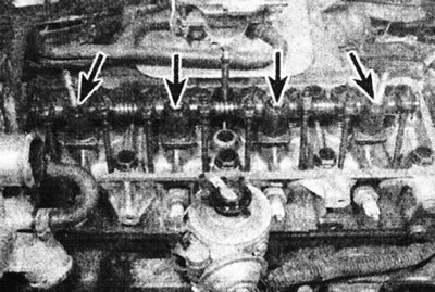
6.18. Unscrew two nuts and two bolts (marked with arrows) and remove the rocker arm shaft assembly.
19. Remove the push rods one by one by rotating them (see illustration).
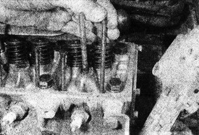
6.19. Remove the push rods and stack them in the order of removal.
Place them in the order they were removed, inserting them into a piece of cardboard with eight numbered holes. Start numbering the push rods from the flywheel.
20. Loosen the cylinder head bolts by turning them one-half turn at a time in the reverse order to that shown for the tightening sequence (see illustration 6.29c).
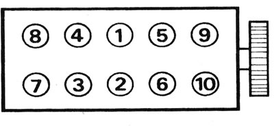
6.29s. Cylinder head bolt tightening sequence.
Remove all bolts except the center bolt on the distributor side.
21. Using a mallet, tap the edges of the cylinder head to loosen it around the remaining bolt. Do not attempt to lift the head until you have done this, otherwise the cylinder liner seal will be damaged and water and foreign particles will enter the oil pan.
22. After freeing the cylinder head from the gasket, remove the remaining bolt and lift the head together with the water pump, manifolds and carburetor (see illustration).
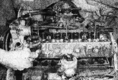
6.22. Loosen the cylinder head, then lift it from the engine.
Note: Do not turn the crankshaft with the head removed, otherwise the cylinder liners will become displaced. If it is necessary to turn the crankshaft (for example, to clean piston heads), secure the sleeves using bolts with wide washers, screwing them into the top of the block. If you have any doubts about the tightness of the sleeve seals, replace the O-rings, following the instructions Part F of this Section.
Inspection
23. The mating surfaces of the cylinder head and block must be completely clean. Use a scraper to remove any remaining gasket material and carbon deposits, and clean the tops of the pistons. Work especially carefully to avoid scratching the aluminum surface of the cylinder head. Also, make sure that no dirt has entered the oil passages and cooling passages - this is especially important for the lubrication circuit, as carbon particles can block the oil supply to the camshaft, rocker shaft, rocker arms or crankshaft bearings. Using masking tape and paper, seal all holes in the cylinder block. Also clean the piston heads.
24. Check the block and head for deep scratches and other damage.
25. If the cylinder head is suspected of being warped, check it using the edge of a straightedge. Also check the height of the protruding part of the cylinder liners. If the above defects are present, the cylinder head gasket may burn out. If necessary, see Part F of this Section.
26. Clean all bolt holes in the block. Make sure all oil is removed from them, otherwise there is a risk of damage to the block due to hydraulic pressure when tightening the bolts.
27. Inspect the threads on the bolts and in the cylinder block for damage. If necessary, renew the threads using a tap and die of the appropriate size.
Installation
28. Remove the cylinder liner clamps, make sure that the surfaces of the cylinder head and block are completely clean. Place the new gasket on the cylinder block with the words "Haut-Top" facing up. Do not use sealant (see illustration).
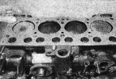
6.28. Place the new head gasket in its operating position.
29. Lower the cylinder head to the working position. Insert the mounting bolts and tighten them gradually to Stage 1 torque in the sequence shown (see illustrations).
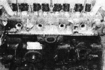
6.29a. Lower the head onto the cylinder block.
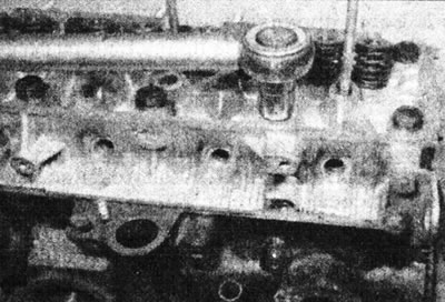
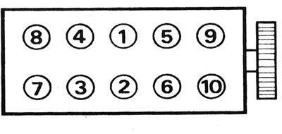
6.29s. Cylinder head bolt tightening sequence.
30. Install the push rods strictly in their original place.
31. Lower the rocker arm shaft assembly onto the cylinder head, making sure the spherical tips are correctly positioned on the push rods (see illustration).
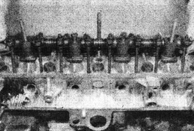
6.31. Lower the rocker arm shaft assembly onto the cylinder head.
Install the spring washers (convex side up), nuts and bolts, and gradually tighten the fasteners to the tightening torque specified in the Specifications.
32. Adjust the valve clearances as described in Chapter 4.
33. Install the valve cover using a new gasket and tighten the nuts.
34. Attach the front section of the exhaust system to the manifold, then install the retaining springs and tighten the bolts. See if necessary. Section 4A.
35. Install the wiring holder onto the cylinder head and secure it with the bracket and bolt.
36. Connect the distributor wiring.
37. Connect the crankcase ventilation hose and fuel inlet line to the carburetor.
38. Install the heat-insulating shield (where available), and tighten the nut and washer.
39. Connect the brake booster hose to the intake manifold.
40. Connect the throttle cable, choke cable and vacuum line to the carburetor as described in Section 4A.
41. Connect the upper radiator hose to the water pump and tighten the clamp.
42. Install the bracket onto the valve cover, then connect the two heater hoses to the water pump and tighten the clamps.
43. Install the generator and drive belt. Adjust the drive belt tension.
44. Connect the wire to the coolant temperature sensor on the water pump.
45. Install the distributor cap and connect the high tension wires to the spark plugs.
46. Install the air filter as described in Section 4A.
47. Fill the engine with oil as described in Section 1.
48. Install the drain plug in the cylinder block, then fill the cooling system as described in Section 1.
49. Connect the wiring to the battery (start with the positive). Start the engine and let it run for 20 minutes, then turn it off and wait at least two and a half hours for it to cool down. Remove the valve cover.
50. Loosen and tighten each cylinder head bolt in turn to the Stage 3 torque, i.e. loosen and tighten bolt 1, then bolt 2, and so on.
51. Recheck the valve clearances and adjust them if necessary (see Chapter 4). Finally, install the valve cover.
[Text of the original source on this website www.RenaultBook.ru]