



Removal
1. Loosen the generator mounting bolt and adjusting lever, push the generator toward the engine, and remove the drive belt from the pulleys. Remove the bolt securing the alternator adjustment lever to the water pump and move the alternator away from the engine (see illustrations 6.7a and 6.7b).
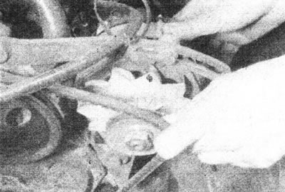
6.7a. Loosen the generator fasteners and remove the drive belt from the pulleys.
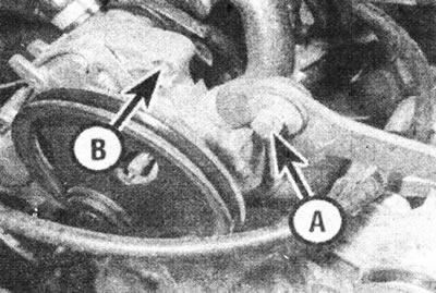
6.7b. Loosen the bolt (A) and disconnect the generator adjustment lever from the pump (B).
2. Remove the pan as described in Chapter 7.
3. Following Chapter 3, turn the crankshaft and set piston No. 1 to TDC on the compression stroke.
4. To prevent the engine from rotating, block the flywheel ring gear with a wide screwdriver by inserting it between the teeth and the crankcase. Alternatively, put the car in 4th gear and have an assistant press the brake pedal. Loosen the crankshaft pulley mounting bolt - it is very tightly clamped.
5. Remove the pulley and hub. If you cannot remove the hub manually, carefully pry it off using two screwdrivers or a two- or tripod puller (see illustration).
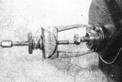
5.5 A special tool may be required to remove the crankshaft pulley hub.
6. Unscrew the nuts and bolts securing the drive cover to the cylinder block. Gently press the lid and remove the gasket (where available).
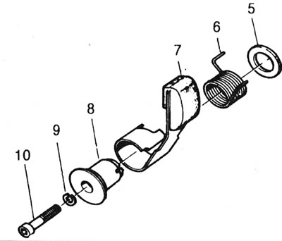
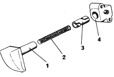
7. Examine the components of the drive chain tensioning mechanism. Keep in mind that one of two types of mechanisms may be used. Mechanical can be identified by the tension spring and one mounting bolt. The automatic hydraulic tensioner can be identified by its piston plunger and two mounting bolts (see illustrations).
5.7a. Components of the hydraulic timing chain tensioner: 1 - Piston with tensioning mechanism shoe; 2 - Spring; 3 - Bushing; 4 - Tension mechanism body.
5.7b. Components of a mechanical timing chain tensioner: 5 - Washer; 6 - Spring; 7 - Shoe lever; 8 - Flange bushing; 9 - Washer; 10 - Mounting bolt.
8. To remove the mechanical tensioner, Renault technicians use a special tubular tool that fits over the tensioner mechanism and spring, holding all components together until the assembly is reinstalled (see illustration).
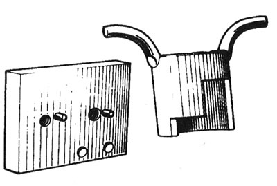
5.8 Renault tool for holding mechanical tensioner components.
If you don't have such a tool, simply loosen the mounting bolt with an Allen key while holding the tensioner shoe and spring end together, and remove the assembly from the cylinder block.
9. If a hydraulic tensioner is installed, lock the plunger by twisting the housing with wire. Loosen the mounting bolts and remove the tensioner mechanism. Remove the mesh filter from the hole in the cylinder block.
10. Bend back the locking tab, then unscrew and remove the camshaft sprocket mounting bolt. Remove the washer. Remove the sprocket and chain from the camshaft, then remove the chain from the crankshaft sprocket (see illustration).
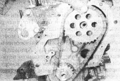
5.10. Remove the drive chain and sprockets.
To remove the sprocket from the crankshaft, use two screwdrivers or a puller.
11. After removing the sprockets and chain, check how the woodruff key is secured in the groove at the end of the crankshaft. If it fits loosely, remove it.
Inspection
12. Inspect the drive chain. Chain wear can be assessed by checking its lateral deflection. Replace the chain if the mileage is more than 50,000 km, or if it makes noise during operation.
13. Inspect all teeth on the camshaft and crankshaft sprockets. If they are "hook-shaped", replace the sprockets. It is recommended to replace the sprockets and chain as a set.
14. If a mechanical tensioner is installed, inspect the contact block. Replace the tensioner assembly if the shoe is severely worn or if the spring is weak.
15. If a hydraulic tensioner is installed, disassemble it by loosening the brake shoe piston with a 3 mm Allen key. Inspect the piston, spring, bushing, and bore in the tensioner housing for scratches. If any damage is found, replace the components. Also replace the tensioner mechanism if the chain contact shoe is severely worn.
16. If the hydraulic tensioner is serviceable, lubricate and reassemble the components. First, lock the bushing into the brake shoe piston by turning it clockwise with an Allen key, then insert this assembly into the tensioner housing. Try not to press on the shoe now, otherwise the bushing will be released and the assembly components will fly apart under the action of the spring. The new hydraulic tensioner has a 2mm thick safety spacer that is inserted between the shoe and the tensioner housing.
17. Replace the seal in the drive cover by pressing out the old one with a suitable punch. Install the new seal using a large socket or a block of wood (see illustration).
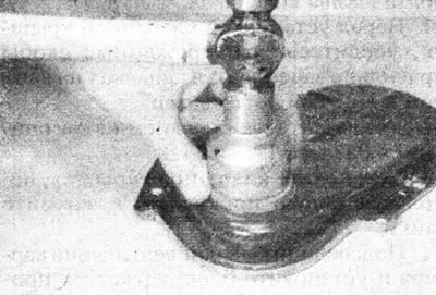
5.17. Use a socket or pipe to replace the drive cover seal.
Installation
18. Install the woodruff key into the crankshaft keyway, then push the crankshaft sprocket into place. The sprocket must be installed so that the timing mark on it faces away from the engine.
19. Turn the crankshaft, if necessary, until the notch on the flywheel aligns with the TDC mark on the scale.
20. Temporarily place the camshaft sprocket in the working position. Rotate the camshaft so that the timing marks on the sprocket surfaces are positioned as shown (see illustration).
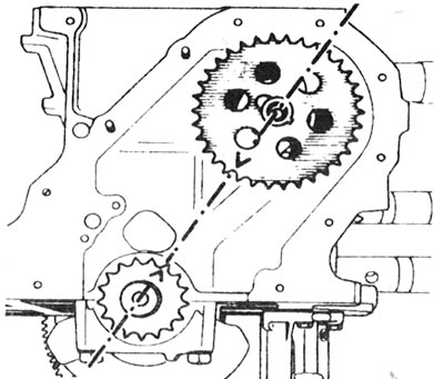
5.20. Location of timing marks with correct position of crankshaft and camshaft sprockets.
Remove the camshaft sprocket.
21. Install the drive chain onto the camshaft sprocket, orient the sprocket to approximately the correct position, and place the chain onto the crankshaft sprocket. Place the sprocket on the camshaft and ensure that the marks are aligned when the chain sag is equal on both sides.
22. Install the camshaft sprocket bolt using a new locking tab and tighten the bolt to the specified torque. Bend the locking tab upwards and secure the bolt.
23. If a mechanical tensioner is installed, place it in the operating position and install the spring ends into the block and onto the shoe lever. Install the mounting bolt and tighten it securely with an Allen key.
24. If a hydraulic tensioner is installed, first insert the strainer into the cylinder block (see illustration).
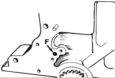
5.24. Location of the mesh filter (F) for the hydraulic tensioner in the cylinder block.
Remove the safety spacer gasket (when installing a new tensioning mechanism) and place the tensioner mechanism on the cylinder block. Insert and tighten the bolts. Push the shoe all the way in, then release it. The piston should come out under the force of the spring.
25. Lubricate the chain, sprockets and tensioner mechanism. Make sure the mating surfaces of the drive cover and cylinder block are clean and dry and remove any remaining old sealant. A new seal must be installed in the drive cover.
26. If the drive cover does not have locating pins, a gasket must be installed. Place the gasket on the cylinder block, securing it with grease. Install the drive cover and tighten the nuts and bolts by hand. Lubricate the pulley hub and temporarily install it on the end of the crankshaft to allow the drive cover to be positioned correctly, then tighten the cover nuts and bolts.
27. If there are mounting pins, apply CAF 4/60 THIXO paste to the surface of the drive cover (see illustration), then place the lid on the pins and two studs. Tighten the nuts and bolts gradually in a diagonal sequence.
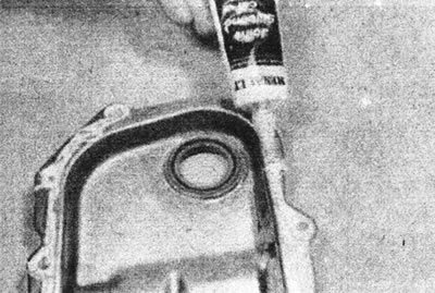
5.27. Apply sealant to the surface of the drive cover.
28. Lubricate the crankshaft pulley hub and carefully place it on the end of the crankshaft (see illustration).
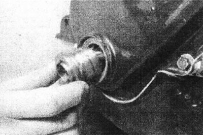
5.28. Place the pulley hub onto the end of the crankshaft...
29. Place the pulley in the working position, install the mounting bolt and washer, and tighten the bolt to the tightening torque specified in the Specifications (see illustrations).
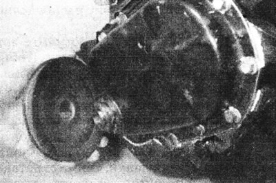
5.29a....then install the pulley...
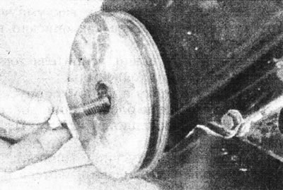
5.29b....and the mounting bolt.
Support the crankshaft using one of the methods described in step 4.
30. Install the tray, see Chapter 7.
Text of the original source on this website: renaultbook
31. Install and tension the alternator drive belt.