
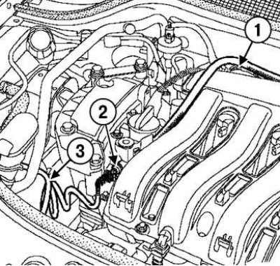
Pic. 2.214. The scheme for connecting devices when checking an electric fuel pump: 1 - pipeline with a pressure gauge; 2- «tee» instrument (Mot. 1311–08); 3 - fuel supply line
Connect the piping with the pressure gauge from the test kit (Mot. 1311-01) To «tee» instrument (Mot. 1311-08) and fuel supply line «tee» rail pipe (pic. 2.214).
Attention! Carry out the test procedure with the engine not running.
Remove the cover of the Protection and Switching Unit.
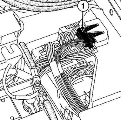
Pic. 2.24. Connector Removal: 1 - connector
Disconnect the brown connector of the Protection and Switching Unit (see fig. 2.24).
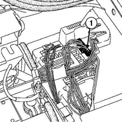
Pic. 2.25. Disconnecting the switching unit connector: 1 - connector
Connect the brown connector pin to the terminal «+» battery to drive the fuel pump (see fig. 2.25).
Measure the pump output, which should be 80–120 l/h.