



Contents: Inspection 🠛 Replacement 🠛
Warning: Brake pads should be changed on both rear wheels at the same time - changing pads on only one wheel will result in uneven braking. Dust generated by brake pad wear may contain asbestos, which is harmful to health. Never blow it out with compressed air and try not to inhale it. DO NOT use mineral solvents to clean brake components. Use only a special cleaner or methyl alcohol.
Inspection
1. Remove the brake drum (Chapter 13).
2. Carefully remove dust from the drum, support shield and shoes.
3. Measure the thickness of each brake pad (including metal base) in several places. If any one of the pads is worn to the minimum thickness specified in the Specifications or is contaminated with oil or grease, replace all four rear brake pads.
4. If one of the brake pads is worn unevenly or contaminated with oil, find and correct the cause.
Replacement
Note: Suitable high temperature brake lubricant or anti-lock compound will be required during installation.
5. The procedure depends on the type of brake unit.
Bendix brake pads
6. Using pliers, remove the spring support cups of the leading and driven shoe support struts by pressing them down and turning them 90°. Remove the springs, then pull out the support struts.
7. Carefully release the shoes (one at a time) from the lower anchor plate to relieve tension on the return spring, then disconnect the lower return spring from both shoes (see illustration).
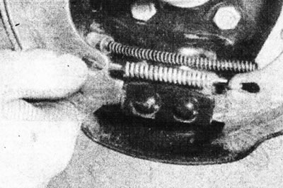
14.7 On Bendix rear brakes, carefully release the shoes from the lower anchor plate and disconnect the lower return spring.
8. Release both pads from the wheel cylinder, being careful not to damage the cylinder seals. Disconnect the handbrake cable from the driven shoe. Remove the brake pad and spreader bar assembly from the brake backing plate. Do not press the brake pedal until you have reassembled the brake assemblies; place a tight rubber band on the cylinder to prevent the pistons from coming out.
9. Place the brake pad assembly on a work bench and mark the location of the springs and the spreader bar to facilitate subsequent installation. Release the handbrake lever limiter (if not already done), then separate the retaining spring of the expansion bar bolt from the leading brake shoe. Disconnect the upper tension spring, then separate the leading shoe and spring from the driven shoe and spreader bar. Disengage the spring that secures the spreader bar to the driven brake shoe and separate the components.
10. If original brake pads are being installed, it is necessary to remove the handbrake lever from the old driven pad and install it on the new pad. Attach the lever to the working position using the new bracket supplied with the pads. All tension springs should be replaced, regardless of their condition.
11. Remove the adjuster bolt from the expansion bar and carefully inspect the assembly for damage or wear, paying particular attention to the bolt threads and knurled wheel. Replace components if necessary. Please note that the left and right brake caliper plates and adjuster bolts are not interchangeable. The planks are marked with the letters "G" (left brake) и "D" (right brake); the bolt on the left bar has a left-hand thread, while the bolt on the right bar has a right-hand thread. The left bar bolt may be indicated by a groove on the flange of the adjuster wheel (see illustration).
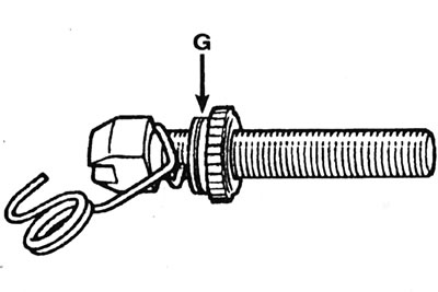
14.11. The bolt of the left expansion bar can be marked with a groove (G) on the flange of the regulator wheel (bendix rear brake).
The right bolt does not have a groove, but it is painted.
12. Make sure the components at the end of the expansion bar are installed correctly (see illustration), then apply a small amount of high temperature grease to the threads of the adjuster bolt. Screw the adjuster wheel onto the bolt, leaving only a small gap between the wheel and the head of the bolt, then install the bolt onto the bar.
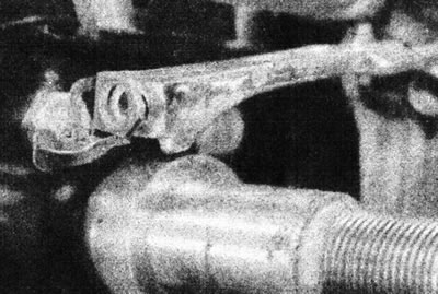
14.12. Correct placement of Bendix expansion bar components.
13. Attach the shorter hook of the expansion bar retaining spring to the driven shoe. Attach the expansion bar to the end of the spring, then place the bar in the working position (into the groove of the driven shoe).
14. Attach the upper tension spring to the driven shoe and then to the leading shoe. Move the leading brake shoe down so that the head of the adjuster bolt fits into its groove. Attach the bolt retaining spring to the drive shoe.
15. Remove the rubber band installed on the working brake cylinder. Pull back the rubber protective caps and inspect the wheel cylinder for damage or leaks. Make sure both pistons move freely in the cylinder. Replace the slave cylinder if necessary (see Chapter 15).
16. Before installation, clean the brake backing plate and apply a small amount of high-temperature grease or anti-lock compound to all pad contact surfaces of the backing plate, as well as the slave cylinder pistons and lower anchor plate (see illustration).
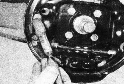
14.16. Apply a small amount of high-temperature grease to the areas of the support shield that contact the pads.
Carefully dispense the composition so that the lubricant does not get on the brake linings.
17. Make sure that the handbrake lever stop rests against the edge of the driven shoe.
18. Place the expansion bar and shoe assembly in the working position. Connect the upper ends of both pads to the pistons of the working cylinder. Attach the handbrake cable to the lever on the driven shoe. Install the lower tension spring and place the shoes behind the lower anchor plate (see illustration).
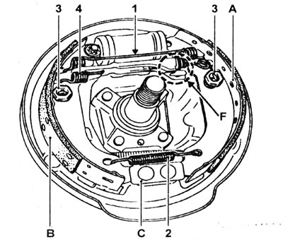
14.18. Bendix Rear Brake Component Locations: A - Leading shoe; B - Driven shoe; C - Lower anchor plate; F - Expanding bar mechanism; 1 - Upper tension spring; 2 - Lower tension spring; 3 - Brake shoe support post, its spring and support cup; 4 - Spring securing the expansion bar to the driven brake shoe.
Material is located on the source website: renaultbook.ru
19. Center the pads on the support shield. Install the brake pad support posts and their springs, then secure them with the support cups.
20. Using a screwdriver, turn the adjusting wheel of the expansion bar so that the diameter of the circle formed by the pads is 179.2 - 179.5 mm.
21. Place the drum in the working position, but do not install the hub nut yet.
22. Repeat the above procedure on the second rear brake.
23. Adjust the clearance between the pads and the drum by pressing the brake pedal several times. Have an assistant check that the spreader bars are functioning properly (when you press the pedal, the expansion bar adjuster should click).
24. Remove the rear drums and check that the handbrake lever stops are still in contact with the driven shoes and that the levers move easily. If all is well, with the help of an assistant, adjust the handbrake cable so that the brake operating levers on each of the rear brake assemblies begin to move when the interior lever moves between the first and second teeth of the ratchet. When finished, tighten the lock nut securely while holding the adjusting nut still. Where necessary, install an exhaust system heat shield.
25. Install the brake drums as described in Chapter 13.
26. Finally, check the brake fluid level.
Girling pads
27. Draw the location of the springs and the expansion bar to facilitate subsequent installation.
28. Carefully unhook both tension springs and remove them from the brake pads.
29. Using pliers, remove the spring support cup of the leading shoe support post by pressing it and turning it 90°. Remove the spring, then pull out the shoe support post and remove the shoe from the support shield. Unhook the regulator lever spring and remove it from the drive shoe.
30. Separate the expansion bar and remove it from the driven shoe.
31. Remove the support cup of the driven shoe support spring, as well as the spring and the support itself as described above, then separate the handbrake cable and remove the shoe. Do not press the brake pedal until you have reassembled the brakes; put a tight rubber band on the working cylinder to prevent the pistons from jumping out.
32. If you are installing genuine Renault brake pads, you must remove the adjuster lever from the old leading pad and install it on the new pad. All tension springs should be replaced, regardless of their condition.
33. Remove the forked end of the expansion bar. Carefully inspect the assembly for damage and signs of wear, paying particular attention to the adjuster threads and its knurled wheel. Replace components if necessary. Please note that the left and right brake spreader bars are not interchangeable; the left fork has a right-hand thread, and the right fork has a left-hand thread. The forks are also color-coded: the left fork is silver, while the right one is gold.
34. Remove the rubber band installed on the slave cylinder. Peel back the rubber protective caps and inspect the cylinder for damage or leaks. Make sure both pistons move freely in the cylinder. If necessary, replace the cylinder (see Chapter 15).
35. Before installation, clean the brake backing plate and apply a small amount of high-temperature grease or anti-lock compound to the areas where it contacts the pads, as well as to the pistons of the working cylinder and the lower anchor plate. Do not allow grease to come into contact with the brake linings.
36. Make sure that the handbrake lever stop is in contact with the edge of the driven brake shoe.
37. Connect the upper end of the driven shoe to the piston of the working cylinder, then install the shoe support post, its spring and secure them with the support cup. Attach the handbrake cable to the lever.
38. Turn the adjuster wheel to achieve the minimum length of the expansion bar, then place the bar in the working position on the driven shoe. Rotate the forked end of the expansion bar so that the slot in the fork aligns with the drive shoe adjuster lever (see illustration).
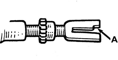
14.38. On rear Girling brakes, the slot in the fork of the expansion bar (A) must fit onto the lever of the leading shoe adjuster.
39. Install the shorter spring hook onto the leading shoe adjuster lever.
40. Place the leading brake shoe assembly in the operating position, ensuring that it engages the fork of the expansion bar and that the slot of the fork fits onto the adjuster lever. Connect the upper end of the shoe to the piston of the working cylinder, then attach the shoe to the working position with a support post.
41. Install the upper and lower tension springs, then tap the shoes to center them on the backing plate.
42. Using a screwdriver, turn the adjusting wheel of the expansion bar so that the diameter of the circle formed by the pads is 178.7 - 179.2 mm.
43. Place the drum in the working position, but do not tighten the hub nut yet.
44. Repeat the above procedure on the second rear brake.
45. Follow the procedures described in paragraphs 23-26.
All brake pads
46. If new pads have been installed, full braking performance will not be achieved until the brake linings have been bedded in. Be prepared for longer braking distances and avoid hard braking for the first 150 km after replacing the pads.