



Removal
Protect your upholstery (for example, with a mastic knife).
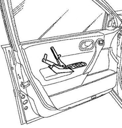
Fig. 8.51. Removing the window switch panel
Disconnect the window switch panel (in the back) pliers for removing upholstery and trim holders (Fig. 8.51).
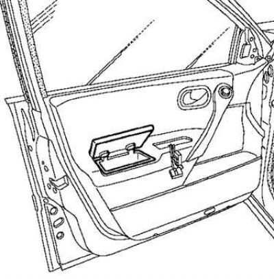
Fig. 8.52. Removing the holder inside the storage compartment
Remove the holders inside the storage compartment (Fig. 8.52).
Insert your hand all the way into the bottom of the storage compartment.
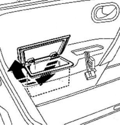
Fig. 8.53. Shifting the storage compartment towards the inside of the door frame
Move the storage compartment towards the inside of the door frame until the compartment comes off (Fig. 8.53).
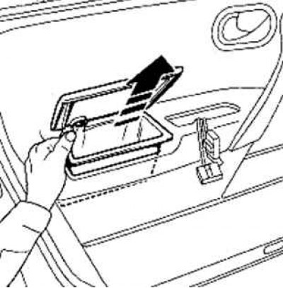
Fig. 8.54. Removing the storage compartment
Remove the storage compartment from the socket (Fig. 8.54).
Caution: Do not pull on the glove compartment lid.
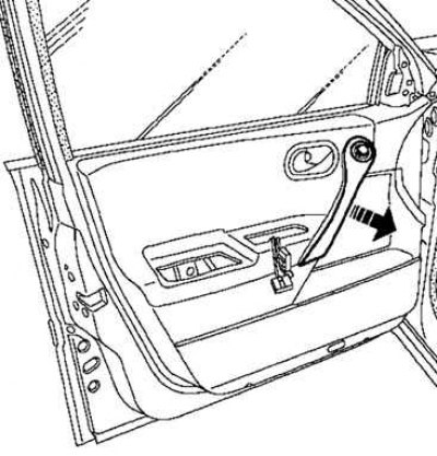
Fig. 8.55. Removing the armrest handle cover
Detach the armrest handle cover (Fig. 8.55).
Disconnect the outside rearview mirror switch connector.
Loosen the screws securing the switch.
Remove the cover.
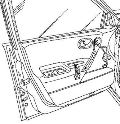
Fig. 8.56. Removing the inner door handle
(Original article is on the portal: RenaultBook)
Loosen the screw securing the inner door handle (Fig. 8.56).
Note: Do not remove the inside door handle cable.
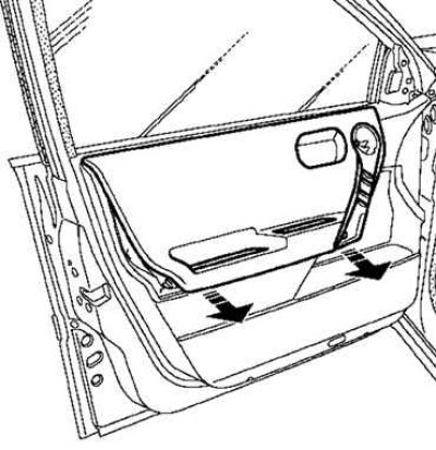
Fig. 8.57. Removing the door trim hatch
Using trim and panel pliers, detach the door trim hatch (taking care not to damage the upholstery) (Fig. 8.57).
Open the hatch.
Secure the hatch in the open position with duct tape.
Remove the lock cylinder.
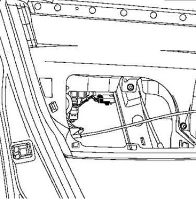
Fig. 8.58. Disconnecting the plug part of the lock activation button connector
Disconnect the plug part of the lock activation button connector (Fig. 8.58).
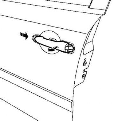
Fig. 8.59. Removing the outer door handle
Disconnect the female connector from the handle and remove it (Fig. 8.59).
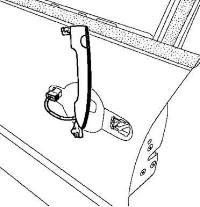
Fig. 8.60. Final disconnection of the door handle
Disconnect the handle, being careful not to damage the connector (Fig. 8.60).
Examination
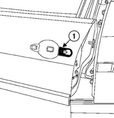
Fig. 8.61. Checking the presence of the handle gasket: 1 – gasket
Before installing the handle, check the presence of the gasket (Fig. 8.61).
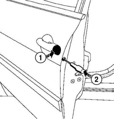
Fig. 8.62. Installing the handle and lock cylinder: 1 – lock cylinder; 2 – locking plate
Install the handle, the lock cylinder and lock its strike plate (Fig. 8.62).
Check the operation of the lock cylinder manually.
Installation
Installation is carried out in the reverse order of removal.