
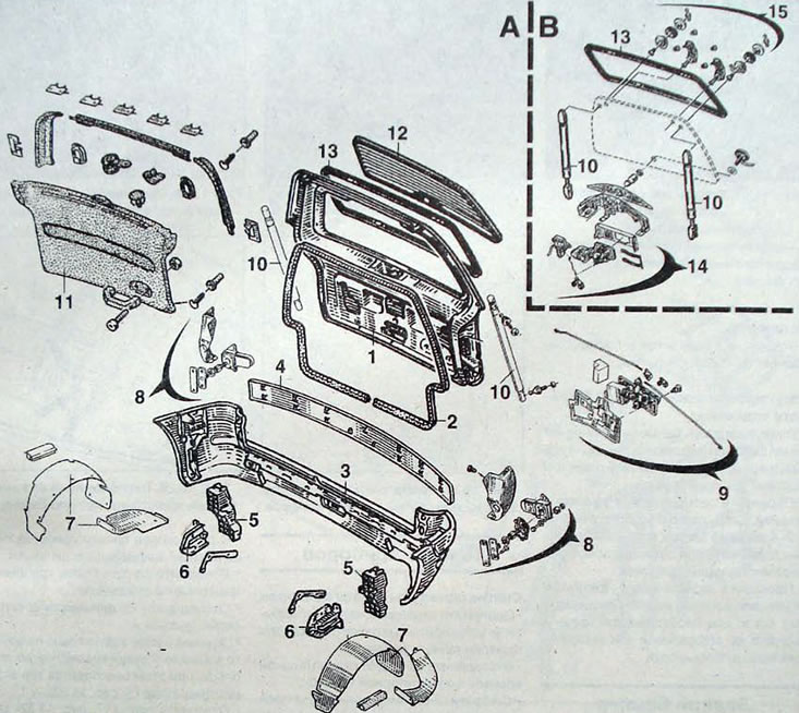
Pic. 13.29. Removable elements of the rear of the car: A - fixed rear window; B - opening rear window; 1 - luggage compartment door; 2 - door seal; 3 - bumper; 4 - door protection trim; 5 - impact energy absorber; 6 - side brackets; 7 - wheel arch liners; 8 - blocking device; 9 - locking mechanism; 10 - door support pillars; 11 - door trim; 12 - rear window; 13 - rear window seal; 14 - rear window opening mechanism; 15 - rear window support elements
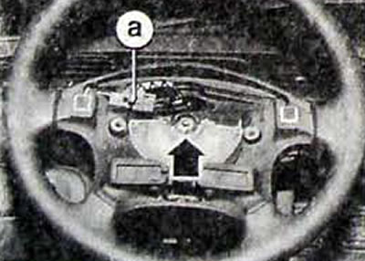
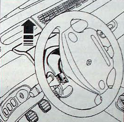
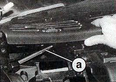
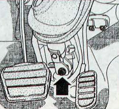
Pic. 13.30. Location of the steering wheel mounting nut with airbag: a - horn switch connector
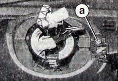
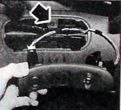
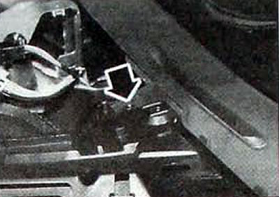
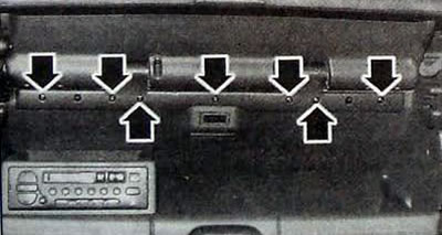
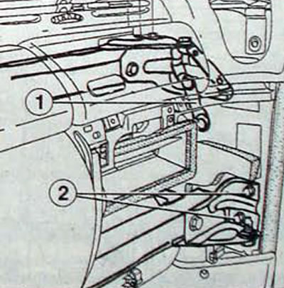
Pic. 13.31. Airbag spiral wire location: a - screw securing the radio control panel
Removing the instrument panel headset
- Raise the front of the car and set the front wheels to drive straight ahead.
- Disconnect the cable from the negative terminal of the battery.
- On the back of the steering wheel, remove the two screws, lift up the airbag, disconnect the electrical connector, and remove the driver's airbag from the center of the steering wheel. Place the pillow in a safe place with the bag facing up.
- Disconnect the connectors from the horn switch and cruise control system.
- Remove the steering wheel mounting nut. Using chalk, a marker or paint, apply alignment marks to the steering wheel and the end of the steering shaft. The marks are necessary to reinstall the steering wheel to its original position.
- Use a puller to remove the steering wheel from the shaft. Do not knock on the shaft or steering wheel when attempting to remove the steering wheel.
- Use adhesive tape to secure the position of the airbag spiral wire. because. Otherwise, it may be misaligned and broken when installing the steering wheel.
- On both sides of the instrument panel, remove the mesh covering the speakers.
- Remove three bolts securing the speaker brackets.
- Disconnect the electrical connectors from the speakers.
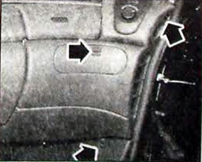
- Starting at a corner, lift the upper trim of the instrument cluster vertically. this will release the three upper latches (1. fig. 13.32).
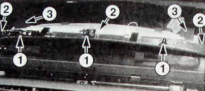
Pic. 13.32. Removing the instrument cluster: 1 - clamps for fastening the trim of the instrument cluster; 2 - rear mounting screws; 3 - side mounting screws
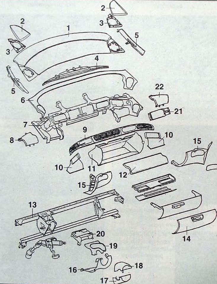
Pic. 13.33. Dashboard: 1 - upper section of the instrument panel; 2 - speaker grilles; 3 - speaker brackets; 4 - instrument cluster; 5 - deflectors for eliminating glass fogging; 6 - overlay; 7 - instrument panel bracket; 8 - cover on the driver's side; 9 - ventilation grilles; 10 - side air ducts; 11 - glove box; 12 - top cover; 13 - beam; 14 - glove box cover; 15 - lower facing; 16 - lower trim of the steering column; 17 - lower casing of the steering column; 18 - upper casing of the steering column; 19 - cover; 20 - steering column bracket; 21 - front passenger airbag; 22 - cover on the front passenger side
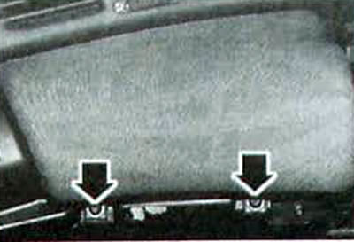
- Remove the screws (2. fig. 13.32) rear mounting of instrument cluster
- Remove the side mounting screws located under the buffers in the sound-absorbing foam.
- Pull the instrument cluster forward
- Disconnect the electrical connectors from the instrument cluster and remove it
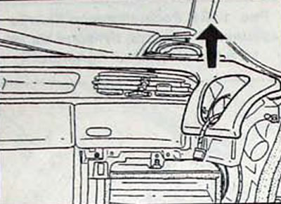
- Remove the screw securing the radio control panel.
- Remove the upper and lower steering column housings (pic. 13.34).
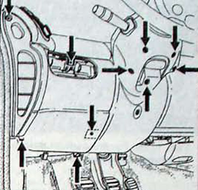
Pic. 13.34. Location of the screws securing the steering column casings and the left lower trim
Pic. 13.35. Removing the upper steering column cover
Pic. 13.36. Removing the switch block from the instrument panel
Pic. 13.37. Location of screws for fastening the right lower trim
Pic. 13.38. Location of the steering column mounting screws
- Remove the switch block from the instrument panel and disconnect the electrical connectors.
- Remove the screws and lower trims on the left and right sides of the instrument panel
- Remove the lower trim under the steering wheel and disconnect the connector from the rheostat for adjusting the brightness of the backlight.
- Remove the fabric cover.
- Remove the driver's side cover (pic. 13.39).
Pic. 13.39. Location of screws securing the driver's side cover
- Remove the left and right heating and air conditioning controls (pic. 13.40).
Pic. 13.40. Location of the screw securing the left heating control panel
Pic. 13.41. Removing the instrument panel trim
Pic. 13.42. Location of the screw securing the de-fogging deflector flap
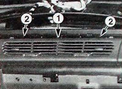
Pic. 13.43. Location of the central ventilation grille fastenings: 1 - screw; 2 - clamps
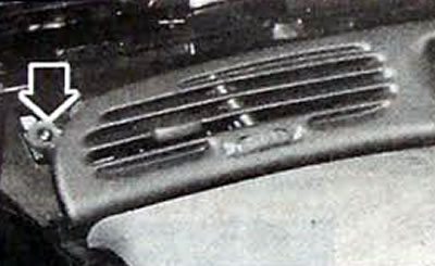
Pic. 13.44. Location of the screw securing the left ventilation grille
Pic. 13.45. Removing the left ventilation grille: a - damper control rod
Pic. 13.46. Location of the ashtray mounting screws on the glove box
- Release and remove the instrument panel trim.
- Remove the de-fog deflector flaps.
- Release two clips each and remove the glass defogging deflectors.
- Unscrew the screw, release the clamps and remove the central ventilation grilles, while the nozzles of the grilles should be closed
- Remove the screw and release the clamps securing the left ventilation grille.
- Carefully remove the left ventilation grille from its slot in the instrument panel
- Remove the right ventilation grill in the same way.
- Remove the front passenger airbag.
- Remove the glove box as follows
- Remove the screws securing the ashtray to the glove box and disconnect the electrical connector from the cigarette lighter.
- Remove the screws securing the glove box lid (Fig 13.47).
Pic. 13.47. Location of the glove box cover screws
- Remove the radio or cassette player and disconnect the electrical connectors
- Remove the sides of the radio box mounting (pic. 13 48).
Pic. 13.48. Location of screws for securing the box for the radio receiver
- Remove the radio box.
- Peel off the glove box carpet and remove two screws (pic. 13.49)
Pic. 13.49. Location of glove box mounting screws
- Remove the glove box.
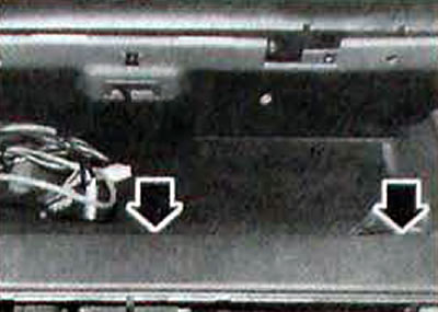
- Remove the two screws securing the instrument panel bracket and remove it.
- Removing the instrument panel beam
Note. Removing the instrument panel beam must be done with an assistant.
Inside the car
- Remove the instrument panel headset.
- Move the front seats all the way back
- Remove 6 screws and remove the front door sills.
- Retract the front of the carpet and soundproof the floor
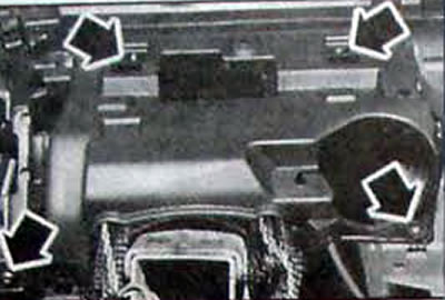
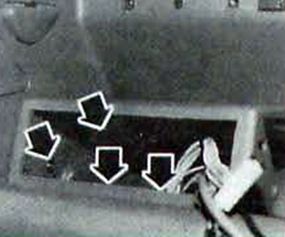
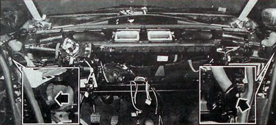
- Remove the screws, remove the fuse and relay box and disconnect the 5 electrical connectors from it (pic. 13.51).
- Remove the fuse/relay box cover and carpet.
- Remove the two bolts securing the hood release handle.
- Disconnect the connector from the ignition switch located under the steering column.
- Disconnect the connectors from the electric motors for the air distribution flaps, as well as the left and right air mixing flaps.
- Disconnect the connectors from the evaporator sensor and the air recirculation motor.
- To access the steering column seal, remove the carpet.
- Be careful to remove the cuff as it has two working edges - one for sound insulation and one for the partition.
- Set the wheels to move in a straight line and from the passenger compartment, unscrew the nut and bolt connecting the steering shaft universal joint fork.
Pic. 13.50. Location of instrument panel bracket mounting screws
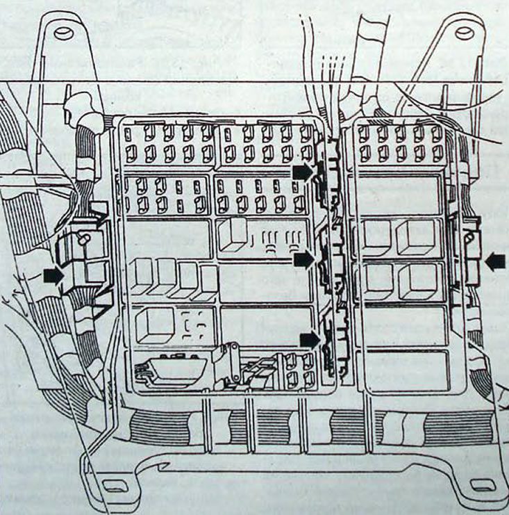
Pic. 13.51. Location of electrical connectors of the fuse and relay box located in the vehicle interior that must be disconnected when removing the instrument panel beam
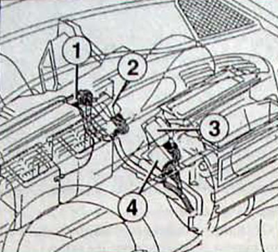
Pic. 13.52. Location of electrical connectors that must be disconnected when removing the instrument panel beam: 1 - evaporator sensor connector; 2 - connector for the electric motor of the air recirculation system; 3 - connector for the electric motor of the air distribution dampers; 4 - air mixing damper motor connector
Pic. 13.53. Location of the nut and bolt securing the steering shaft universal joint to the steering gear
In the engine compartment
- Use clamps to clamp the heater outlet and supply hoses.
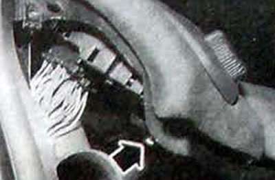
- Disconnect the quick connectors. To disconnect connections, press on the ring brackets and at the same time pull the hoses to the sides to disconnect (pic. 13.54).
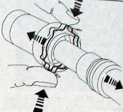
Pic. 13.54. Direction of pressing of the deformable axial locking ring when disconnecting the quick-release connection of the heater outlet and supply hoses on vehicles with F3R engines
- If disconnection is difficult, lightly lubricate the quick connectors before disconnecting.
- On a G8T engine with air conditioning system, the right-hand heater core hose connections cannot be removed manually. To remove the hoses, use tool Mot 1395 as follows (rice 13.55):
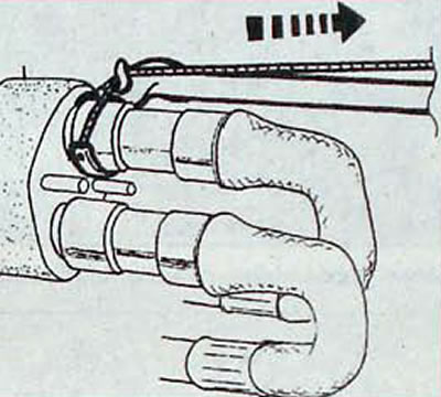
Pic. 13.55. Using tool Mot. 1395 for disconnecting hoses from the fitting of the right heater radiator on vehicles with G8T diesel engines
- pass the strap between the hoses;
- pass the cable through the hook;
- grab the flange behind the fitting;
- Pull the hose and at the same time. a little weaker, by the cable.
- Unscrew the two nuts securing the right and left heater radiators.
- Remove the foam soundproofing.
- Remove the heater cores.
- Remove the panels located under the windshield on the fender side.
- Disconnect and remove the air ducts from the air distribution unit.
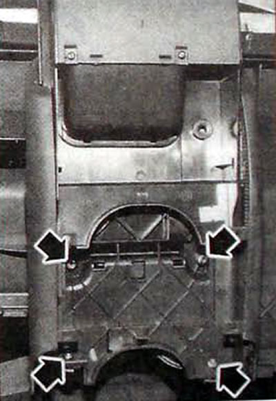
- Unscrew two M8 nuts on both sides of the car (1, fig. 13.56) fastening the upper bracket, do not rotate the beam position adjustment nuts (2).
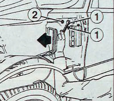
Pic. 13.56. Location of the beam mounting nuts in the front wheel arch: 1 - beam fastening nuts; 2 - beam position adjustment nuts
- Remove the angles from the lower beam mounting.
- Using the blade of a screwdriver as a lever, remove the upper beam mounting bracket.
- Remove the instrument panel beam from the vehicle, while passing the heater connections and the hood lock drive cable through the beam.
- Installing the instrument panel with the beam
- Install the instrument panel beam, ensuring that the heater connections, hood release cable, and all electrical connectors are properly routed through the beam.
- Install the instrument panel beam onto the guide pins.
- Tighten the upper and lower beam fasteners to the required torques.
- Screw in the bolt and nut connecting the steering shaft universal joint fork
- Further installation is carried out in the reverse order of removal. Connect the electrical connectors and check the operation of the electrical equipment
Pic. 13.57. Instrument panel beam fastening elements: 1 - upper beam mounting bracket secured with a nut on the side of the front wheel arch; 2 - bolts for securing the lower angle