



Contents: Removal 🠛 Installation 🠛
Removal
Note: Installation will require a new drive shaft nut and suitable locking compound.
1. Block the rear wheels, apply the handbrake, then jack up the front of the car and place it on axle stands. Remove the front wheel.
2. Install two wheel bolts into the hub and tighten them securely. Remove the drive shaft nut (see Chapter 2 Section 8). Discard the drive shaft nut - it must be replaced.
3. If the wheel bearings need to be removed, remove the brake disc (see Section 9). If this is not the case, remove the two bolts securing the caliper assembly to the steering knuckle and remove the caliper assembly from the disc. Use a piece of wire to tie the caliper to the front suspension spring, being careful not to put tension on the brake hose.
4. On models equipped with ABS, loosen the mounting bolt and remove the front wheel speed sensor from the steering knuckle. Tie the sensor to the suspension strut to avoid damage during removal.
5. Remove the nut securing the steering rod ball joint to the steering knuckle. Remove the ball joint pin using a special puller.
[View the original source on this resource: www.renaultbook.ru]
6. Remove the nut and pinch bolt securing the lower control arm to the steering knuckle (see illustration).
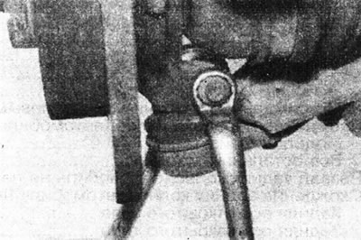
2.6. Loosen the pinch bolt and nut of the lower suspension arm ball joint.
Carefully press the ball joint away from the steering knuckle, being careful not to damage it or the drive shaft protective boots. Note the plastic protective plate installed on the hinge pin.
7. Remove the two nuts and washers from the bolts that secure the steering knuckle to the suspension strut, remembering that the nuts are on the rear side of the strut. Remove the bolts and support the steering knuckle assembly.
8. Displace the drive shaft CV joint from the hub and remove the steering knuckle assembly from the vehicle. Please note that the hinge grooves are coated with a locking compound; use a hammer and a soft metal punch or a puller to remove them.
Installation
9. Make sure the drive shaft joint grooves and hub are clean and dry, then apply locking compound to the joint grooves.
10. Align the grooves of the CV joint and the hub and install the hub on the drive shaft. Insert the two bolts securing the steering knuckle to the suspension strut (from the front side of the rack), then install the washers and nuts on the bolts and tighten them to the specified tightening torque Specifications.
11. Install the washer and new drive shaft nut and tighten it by hand for now.
12. Make sure the plastic plate is still on the lower control arm ball joint, then install the ball joint pin into the steering knuckle. Install the ball joint tie rod and tighten its mounting nut to the specified tightening torque Specifications.
13. Insert the steering rod ball joint into the steering knuckle and tighten its mounting nut to the tightening torque specified in the Specifications.
14. On models equipped with ABS, install the system sensor on the hub and tighten its bolt to the specified tightening torque Specifications (see Chapter 23 Section 9).
15. Install the brake disc (if removed) and securely tighten the screws that hold it in place. Place the brake caliper assembly in the operating position. Apply a few drops of locking compound to the caliper bolt threads. Install the bolts and tighten them to the torque specified in the Specifications (Section 9).
16. Insert and tighten the two wheel bolts. Use them to lock the hub and tighten the hub nut to the tightening torque specified in the Specifications (see Section 8).
17. Make sure the hub rotates freely, then install the wheel and lower the vehicle to the ground. Tighten the wheel bolts to the specified tightening torque Specifications.