



Removal
1. Block the rear wheels, apply the handbrake, jack up the front of the car and place it on axle stands. Remove the front wheel.
2. Disconnect the end of the anti-roll bar from the lower arm as described in previous chapter.
3. Where present, remove the bolt securing the control arm brace to the front fender side member and the nut securing it to the front pivot bolt. Remove the control arm stretcher from the vehicle (see illustrations).
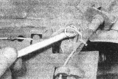
7.3a. Where present, unscrew the upper control arm tensioner mounting bolt...
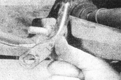
7.3b....and remove the brace from the lower arm pivot bolt.
[Text of the original source on this website: www.RenaultBook.ru]
4. Remove the nut and pinch bolt securing the lower control arm ball joint to the steering knuckle. Carefully pry the ball joint away from the steering knuckle, being careful not to damage the drive shaft boots or the ball joint itself. Remove the plastic protective plate installed on the hinge rod (see illustrations).
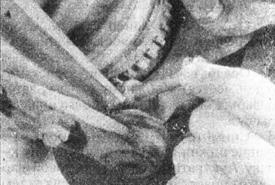
7.4a. Remove the ball joint pinch bolt...
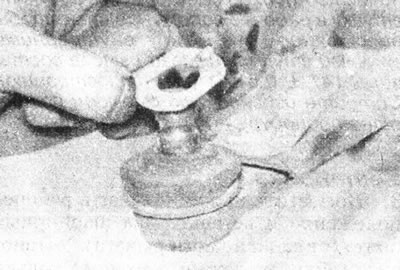
7.4b.... then release the ball joint from the steering knuckle and remove the plastic protective plate.
5. Unscrew the two pivot bolts and their nuts and remove the lower arm from the car (see illustration).
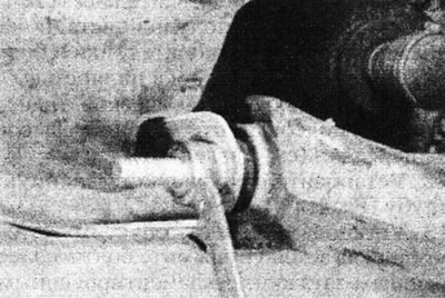
7.5. Unscrew the nuts and remove the lower arm pivot bolts.
Bulkhead
6. Clean the lower control arm and the area around its mountings, then inspect the arm for cracks, deformation, and other damage. On some models, a shield is attached to the lever that deflects air towards the brake disc, which also needs to be removed. Make sure the lower control arm ball joint moves freely and that its protective boot is not damaged. Inspect the pivot bolt shafts for signs of wear and worn areas. Replace worn components as necessary.
7. Inspect the lower control arm pivot bolt bushings. If they are worn, cracked or chipped, replace them. To replace the bushings, support the lower control arm and push out the first bushing using a socket-type spacer resting only on the solid outer edge of the bushing.
Note: Remove only one bushing at a time to ensure proper installation of each new bushing. Thoroughly clean the lower control arm bore and remove any burrs or rough spots that might interfere with assembly. Apply a small amount of suitable grease to the outer edge of the new bushing. Press the bushing into the working position so that the distance "A" between the inner faces of the lower arm bushings is 147±0.5 mm (see illustration). Wipe off excess grease and repeat the procedure on the second bushing.
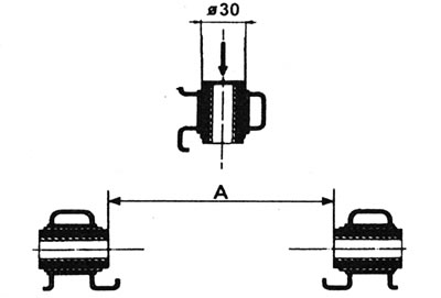
7.7. Correct location of the lower arm pivot bolt bushings. A = 147±0.5 mm.
Installation
8. Place the lower arm in the working position and insert the two pivot bolts (from the back of the lever). Install the nuts, but tighten them only by hand for now.
9. Install a plastic plate onto the lower arm ball joint, then push the ball joint rod into the steering knuckle. Install the hinge clamp bolt and tighten its fastening nut to the specified tightening torque Specifications (see illustration).
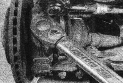
7.9. Tighten the ball joint pinch bolt.
10. Where fitted, install the control arm brace to the front pivot bolt. Tighten the bolt and nut of the fastening.
11. Connect the end of the stabilizer bar to the lower arm, making sure the rubber pads are installed correctly. Do not fully tighten the fasteners yet.
12. Install the wheel, lower the vehicle to the ground and tighten the wheel bolts to the specified tightening torque Specifications.
13. Without jacking up the vehicle, rock it to adjust the position of the lower control arm components. Tighten the lower control arm pivot bolts and stabilizer bar fasteners to the specified tightening torque Specifications. Attach the lever stretcher (where available) into working position, securely clamping its nut and bolt.