



Contents: Removal 🠛 Installation 🠛
Removal
Note: Suitable tool required - see text.
1. Block the front wheels and select reverse (or "P"). Jack up the rear of the car and support it on axle stands. Remove the wheel.
2. Remove the rear shock absorber (see Chapter 10).
3. On models with an open torsion bar, unscrew the mounting screws and remove the clamp securing the handbrake cable to the torsion bar.
4. Pry the cover away from the trailing arm bearing bracket to gain access to the end of the torsion bar.
5. Mark the position of the torsion bar relative to the bearing bracket. On an open rear axle, also mark the position of the torsion bar relative to the central junction block. Without supporting the trailing arm, measure the distance between the centers of the holes for the upper and lower shock absorber mounting bolts - this is necessary for installation.
[Material taken from an online portal: RenaultBook.ru]
6. Remove the torsion bar using a sliding hammer such as the Renault Emb.880 tool (see illustration).
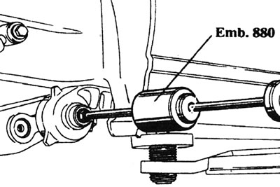
12.6. Remove the torsion bar using a sliding hammer (renault Emb.880 shown).
7. Once the torsion bar grooves are clear, pull it out completely. Please note that the left and right torsion bars are not interchangeable; they may have corresponding marks at the ends (see illustration).
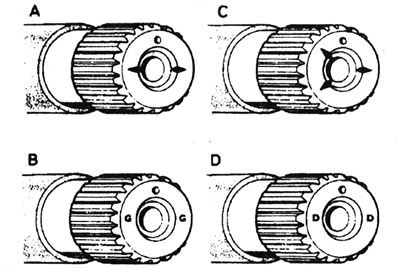
12.7 Rear suspension torsion bar identification marks: A and B - Left torsion bar; C and D - Right torsion bar.
Installation
8. Make sure the bearing bracket and torsion bar grooves are clean and dry. Lubricate the grooves with molybdenum grease and insert the torsion bar into the bracket.
9. If the same torsion bar is being installed, position the trailing arm so that the distance between the centers of the holes for the upper and lower shock absorber mounting bolts matches the value measured before removal.
10. If installing a new torsion bar, raise the trailing arm so that the distance "X" between the centers of the holes for the upper and lower shock absorber mounting bolts is 400 mm (on models with F7P engine - 372 mm).
11. Raise the trailing arm to the required position using a jack. Alternatively, make a tool similar to the one shown from a piece of threaded rod (see illustration).
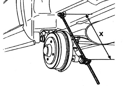
12.11. Homemade tool for setting the distance "X" - see text.
The old torsion bar
(all types)12. Rotate the torsion bar to align the marks made before removal, then connect it to the bearing bracket and the bearing/center joint block grooves. Drive the torsion bar fully into its working position using a hammer and a soft metal punch.
New torsion bar
(closed rear axle)13. Rotate the torsion bar until you find a position where it can be freely inserted into the grooves on the bearing bracket and the bearing itself. Drive the torsion bar fully into its working position using a hammer and a soft metal punch.
New torsion bar
(open rear axle)14. Remove the cover of the opposite bearing bracket and check the position of the mark on the end of the torsion bar (see illustration).
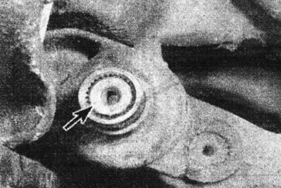
12.14. Check the position of the round mark (marked with an arrow) at the end of the torsion bar.
Rotate the new torsion bar until its mark is in the same position, then align its grooves with those of the bearing bracket and the center connecting block and insert the torsion bar. If necessary, slightly turn the torsion bar, remembering that the marks on both torsion bars should be no more than two notches apart from each other. If this is not possible, it is permissible to slightly lower or raise the trailing arm. If significant lever movement is required to align the slots, it is recommended to also replace the opposite torsion bar.
15. Drive the torsion bar into position using a hammer and a soft metal punch.
All types
16. Install the torsion bar caps onto the bearing bracket.
17. On models with an open torsion bar, install the handbrake cable mounting clamp onto the torsion bar and tighten its screws securely.
18. Install the rear shock absorber (see Chapter 10).
19. Check the rear suspension overhang (see Chapter 17).