



Rear suspension with closed torsion bars
2. Only the rear suspension overhang can be adjusted in 3 mm increments. First, measure and record the H4 and H5 values on both sides of the car, remembering that the H5 value is measured from the center of the torsion bar (see illustration).
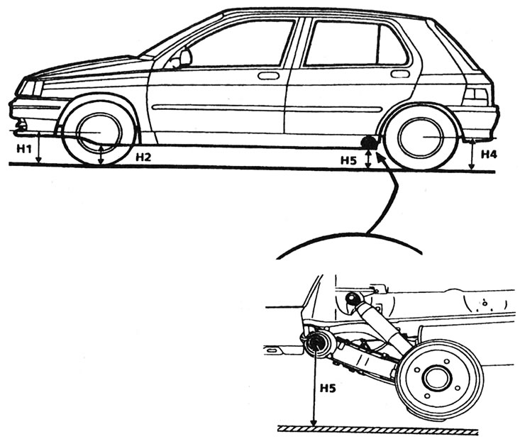
17.2. Rear suspension overhang measurement points - please note that H5 is measured from the center of the torsion bar.
Subtract H5 from H4 to calculate the rear suspension overhang. Make sure the result is within the range given in Specifications. If adjustment is necessary, proceed as follows.
3. Determine how many notches the torsion bar should be moved, remembering that one notch changes the height by 3 mm.
4. Block the front wheels and select reverse (or "P"). Jack up the rear of the car and support it on axle stands. Remove the rear wheel.
5. Support the end of the trailing arm with a jack, then remove the torsion bar (see Chapter 12). Raise or lower the trailing arm as required so that it rotates relative to the bearing bracket by the required number of notches. Slightly change the position of the trailing arm so that the torsion bar moves freely into its working position. Use a hammer and a soft metal drift to drive the torsion bar into place.
6. Install the wheel, lower the vehicle to the ground and tighten the wheel bolts to the torque specified in the Specifications.
7. Recheck the rear suspension overhang. If necessary, repeat the adjustment procedure. Please note that after completing the adjustment, it may be necessary to adjust the direction of the headlight beam (see Section 1).
Rear suspension with open torsion bars
8. Measure and record the values of H4 and H5 on both sides of the car, remembering that the height of H5 is measured from the center of the torsion bar (see illustration 17.2). Subtract H5 from H4 to get the rear suspension overhang. Make sure the result is within the range given in the Specifications. Please note that on these models, the maximum difference between the measurements on each side is 5 mm. If necessary, adjust the height as described below.
The rear suspension overhang is correct on both sides of the car, but the difference between the sides is excessive - new rear axle assembly
9. The difference between the right and left sides is corrected by changing the position of the anti-roll bar on the lower side so as to raise it level with the other side. Calculate the height difference between the two sides, then adjust the overhang as follows.
10. Mark the position of the two torsion bars and the stabilizer bar to be removed relative to the center junction block and trailing arm/bearing bracket.
11. Remove both torsion bars (see Chapter 12), then remove the desired anti-roll bar.
12. Make sure the "X" distance is set correctly on both sides (see paragraphs 10 and 11 of Chapter 12). Measure the distance from the center of the steering knuckle to the ground on the side where the stabilizer was removed. Subtract the difference in height between the sides from this measurement to get the correct height at which the steering knuckle should be, then lower the trailing arm until the knuckle is at that height.
13. Install the stabilizer by rotating it to a position where it fits freely into the grooves and drive the stabilizer completely into the working position. Using the marks made prior to removal, ensure that the offset of the stabilizer bar grooves matches the distance the trailing arm was moved (see table).
| Trailing arm offset (mm) | Number of grooves |
| 5 | 2 |
| 10 | 4 |
| 15 | 6 |
| 20 | 8 |
| 25 | 10 |
| 30 | 12 |
| 35 | 14 |
| 40 | 16 |
| 45 | 18 |
| 50 | 20 |
14. Align the marks made before removal, then install both torsion bars.
15. Install the shock absorbers as described in Chapter 10.
16. Install the wheels, lower the vehicle to the ground and tighten the wheel bolts to the specified torque Specifications.
17. Recheck the rear suspension overhang. If necessary, repeat the adjustment procedure. Please note that after completing the adjustment, it is necessary to adjust the direction of the headlight beam as described in see Section 1. It is also recommended to have a specialist check the operation of the pressure regulating valve in the brake system.
The rear suspension overhang is incorrect on both sides of the car, the difference between the sides is excessive - new rear axle assembly
18. Calculate the difference in suspension height between the two sides and the amount by which the higher side deviates from the height specified in the Specifications.
19. Follow the procedures described in points 10-13.
20. Measure the distance from the center of the steering knuckle to the ground on each side. Raise or lower both trailing arms an equal amount so that the height is increased or decreased by the calculated deflection of the higher side (item 18).
21. Install the torsion bars by rotating each one until you find a position where it fits freely, and drive them into the working position. Using the marks made prior to removal, ensure that the offset of the torsion bar grooves matches the distance the trailing arm was moved (see table in point 13).
22. Follow the procedures described in paragraphs 15-17.
The rear suspension overhang is incorrect on both sides of the car, but the difference between the sides is within the acceptable tolerances - new rear axle assembly
23. In this case, the overhang of the rear suspension is adjusted by moving the torsion bars. First, calculate the amount by which the suspension overhang deviates from the height stated in the Specifications.
24. Mark the location of the torsion bars in the center junction block and bearing bracket, then remove both torsion bars (see Chapter 12).
25. Make sure the "X" distance is set correctly on both sides (paragraphs 10 and 11 of Chapter 12). Measure the distance from the center of the steering knuckle to the ground. Raise or lower both trailing arms equally so that the distance is increased or decreased by the calculated deviation (item 23).
26. Install the torsion bars by rotating each one to a position where it fits freely and hammering them into position. Using the marks made prior to removal, ensure that the offset of the torsion bar grooves matches the distance the trailing arm was moved (table in paragraph 13).
27. Follow the procedures described in paragraphs 15-17.
The rear suspension overhang is correct on one side, the difference between the sides is excessive - previous rear axle assembly
28. The difference between the sides is always corrected by raising the anti-roll bar on the side where the suspension is located lower to the level of the other side. Calculate the difference in height between the two sides, then proceed as follows.
29. Remove the rear shock absorbers (Chapter 10). Mark the position of the two torsion bars and the anti-roll bar to be removed on the center junction block and on the bearing bracket/trailing arm.
30. Support the trailing arm with a jack. Remove the torsion bars (Chapter 12) and the required stabilizer.
31. Make sure the component grooves are clean and dry and apply a small amount of molybdenum grease to them.
32. Align the marks made before removal and install the stabilizer. If necessary, slightly raise or lower the trailing arm to find a position where the stabilizer bar fits freely.
33. Measure the distance between the centers of the holes for the upper and lower shock absorber mounting bolts (the "Y" dimension). Remove the stabilizer again.
34. Making sure the "Y" dimension is correct, measure the distance from the center of the steering knuckle to the ground on the side where the stabilizer was removed. Subtract the difference in height between the sides from the resulting value, then lower the trailing arm so that the steering knuckle is at the height calculated in this way.
35. Install the stabilizer by rotating it to a position where it fits freely and drive it into position. Using the marks made before removal, ensure that the offset of the stabilizer grooves corresponds to the distance by which the trailing arm was moved (item 13).
36. Follow the procedures described in paragraphs 14-17.
The rear suspension overhang is incorrect on both sides, the difference between the sides is excessive - previous rear axle assembly
37. Calculate the difference in ride height between the sides of the vehicle and the amount by which the higher side deviates from the specified ride height.
38. Perform the actions described in points 29-35.
39. Measure the distance from the center of the steering knuckle to the ground. Raise or lower both trailing arms equally so that the distance between the steering knuckles and the ground increases or decreases by the calculated deflection of the higher side (item 37).
40. Install the torsion bars by rotating each one to a position where it fits freely. Using the marks made before removal, ensure that the offset of the grooves corresponds to the distance the trailing arm was moved (item 13).
41. Follow the procedures described in paragraphs 15-17.
The rear suspension overhang is incorrect on both sides, but the difference between the sides is within the tolerances - previous rear axle assembly
42. In this case, the overhang of the rear suspension is adjusted by moving the torsion bars. First, calculate the amount by which the suspension overhang deviates from the height stated in the Specifications.
43. Remove the rear shock absorbers (Chapter 10). Mark the position of the torsion bars in the bearing bracket and the center junction block.
44. Support the trailing arm with a jack. Remove the torsion bars (Chapter 12).
45. Make sure the component grooves are clean and dry and apply a small amount of molybdenum grease to them.
46. Align the marks made before removal and install the torsion bars. If necessary, slightly raise or lower the trailing arm to find a position where both torsion bars fit freely.
47. Measure the distance between the centers of the holes for the upper and lower shock absorber mounting bolts (dimension "2").
48. Make sure the "2" dimension is set correctly on both sides, then measure the distance from the center of the steering knuckles to the ground. Raise or lower both trailing arms equally so that the distance between the trunnions and the ground increases or decreases by the height difference (item 42).
49. Install the torsion bars by rotating each one to a position where it fits freely. Using the marks made before removal, ensure that the offset of the torsion bar grooves corresponds to the distance the trailing arm was moved (item 13).
50. Follow the procedures described in paragraphs 15-17.