



General description
1. The relative position of the steering and suspension components is determined by four main indicators (see illustrations). All of these are expressed in degrees, although toe can also be measured on a linear scale. The kingpin axis is an imaginary line drawn through the suspension strut axis.
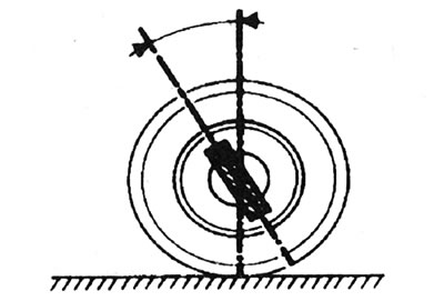
25.1a. Longitudinal inclination of kingpin.
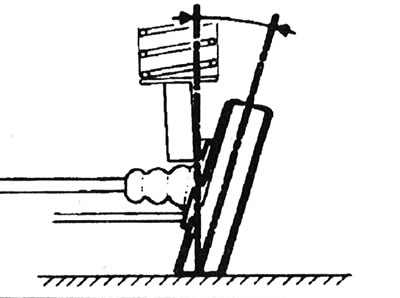
25.1b. Collapse.
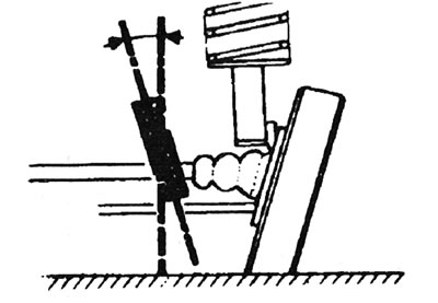
25.1c. Transverse inclination of kingpin.
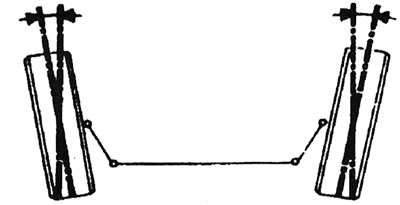
25.1d. Reverse convergence.
2. Camber is the angle by which the plane of rotation of the front wheels deviates from the vertical line when viewed from the front of the car. Camber is considered positive when the tops of the wheels are tilted outward.
3. The camber cannot be adjusted, it can only be checked using a special template. If the camber differs significantly from the specifications, consult your dealer.
4. Kingpin inclination is the angle between the kingpin axis and the vertical line when viewed from the side of the vehicle. The longitudinal inclination of the kingpin is positive when the kingpin axis is tilted backwards.
5. The longitudinal inclination of the kingpin cannot be adjusted, but can also be checked using an appropriate template.
6. Kingpin caster is the angle between the kingpin axis and a vertical line drawn through the center of each wheel, when viewed from the front or rear of the vehicle.
7. The transverse inclination of the kingpin is not adjustable.
8. Toe-in is the deviation of the plane of rotation of the wheels from the longitudinal axis of the vehicle. Toe-in is said to be positive when the front parts of the wheels point inward. About the negative (or vice versa) toe-in is when the front parts of the wheels are pointed away from each other.
9. The toe-in of the front wheels is adjusted by changing the length of the steering rods by moving the ends along them.
10. The toe-in of the rear wheels is not adjustable and, like the kingpin inclination, is provided only to check the geometry of the vehicle.
Check - General Description
11. Since checking and adjusting wheel alignment requires special measuring equipment and a certain amount of skill, it is recommended that this work be carried out by a dealer. If you still decide to do the work yourself, proceed as follows.
12. For the measurement to be accurate, the vehicle must have a nominal weight (see "Weight and dimensions"),
13. Before starting work, make sure the vehicle is equipped with the correct size and type of tires, then check the tread wear and tire pressure. Also check the wheels for runout, the condition of the wheel bearings, the play in the steering wheel and the condition of the front suspension components (Section 1).
14. Park the car on a level spot (not downhill), with the front wheels in a straight-ahead position. Rock both ends of the vehicle to allow the suspension components to settle into place. Release the handbrake and roll the vehicle back 1 metre, then forward again to relieve any tension on the steering and suspension components.
Wheel alignment - checking and adjustment
Front wheels - check
15. There are two templates for checking the front wheel alignment. One measures the distance between the extreme front and rear points of the inner edges of the wheel rims (the difference between these measurements constitutes the convergence). The other is a plate on which each front wheel is rolled, and then the toe is determined by the displacement of the plate. Both templates are regularly available for purchase and are relatively inexpensive.
16. Prepare the vehicle as described in steps 12–14.
17. If using the first template, carefully measure the distance between the front and rear edges of the wheel rims. Subtract the back measurement from the front measurement and make sure the result matches the data given in Specifications. If this is not the case, adjust the toe-in as described in point 19.
18. If using the second template, roll the vehicle backwards, ensure the front wheels are in the straight ahead position, then roll them across the template so that each front wheel is directly centered on its corresponding plate. Record the angle recorded by the template. To ensure accuracy, repeat the measurement three times and calculate the average. If the wheels are parallel, the template will not show any angle. If the value obtained for each wheel differs from that specified in Convergence specifications, adjust the position of the wheels as follows.
Front wheels - adjustment
19. Apply the handbrake, jack up the front of the car and securely place it on axle stands. Turn the steering wheel to the extreme left position and record the number of visible turns of the right tie rod thread. Now turn the steering wheel to the extreme right position and record the number of thread turns on the left rod. If the number of thread turns is the same, then subsequent adjustments must be made equally on both sides. If more threads are visible on one side than the other, this must be compensated for during adjustment.
Note: It is important that after adjustment the same number of thread turns are visible on the rods.
20. First, clean the steering rod threads. Release the outer clamps of the rubber boots, then bend the boots back and apply a small amount of grease so that both protective boots do not become taut when turning the steering rods.
21. Using a ruler and marking tool, mark the alignment marks on each tie rod with its ball joint. After locking the steering rods one by one, completely unscrew their lock nuts.
22. Change the length of the steering rods, taking into account the Note in point 19, by screwing them in or out of the ball joints using a double-ended wrench. Shortening the steering rods (screwing them into ball joints) reduces convergence. Each full turn of the rod changes the toe by 30" or 3 mm (see illustration).
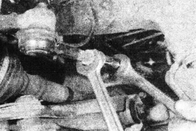
25.22. Adjust the front wheel alignment.
23. When the installation is correct, tighten the tie rods and securely tighten the ball joint lock nuts. Make sure the joints are seated correctly in their sockets and count the number of thread turns on the rods. If the number of revolutions is not the same, the adjustment is not done correctly.
24. Once the correct alignment is achieved, lower the vehicle to the ground and recheck the alignment; repeat the adjustment if necessary. When finished, tighten the hinge lock nuts to the specified tightening torque Specifications. Make sure the rubber boots are positioned correctly and secure them with new clamps.
Rear wheel alignment
25. The procedure for checking the rear toe-in is similar to that described in paragraph 17. However, it cannot be adjusted.