
English Русский
Български
Беларускі
Український
Српски
Hrvatski
Română
Polski
Slovenský
Magyar
Bookmark Contacts Articles Sitemap
Company vehicles Peugeot Company vehicles Opel Company vehicles Skoda Company vehicles Land Rover Company vehicles Mitsubishi Company vehicles Volkswagen Company vehicles Honda
RenaultBook.ru


Duster   Fluence   Kangoo   Laguna   Logan   Megane   Sandero   Scenic   Symbol   Clio   Other
Clio 1 (1990-1998)

Every 58,000 km — check the air temperature control system (Renault Clio 1)

  • Main
  • Clio
  • Clio 1 (1990-1998)
  • General information
  • Maintenance
  • Every 58,000 km — check the air temperature control system
0
Contents: All engines except F3P 🠛 F3P engine 🠛
Note: This procedure only applies to engines with a carburetor or central fuel injection system.


1. For the engine to operate efficiently, the temperature of the air entering the intake system must be maintained at a certain level. (This does not apply to engines with a distributed fuel injection system, where the system compensates for changes in air temperature).

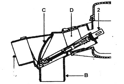
2. The air filter has two air sources, one is outside the engine compartment (cold air), and the other one - from the casing on the exhaust manifold (heated air). The wax thermostat controls the damper inside the inlet duct. When the ambient air temperature is below a certain level, the flap directs warm air away from the exhaust manifold housing. As the ambient temperature rises, the damper opens and begins to let in cold air from outside the car.

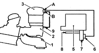
3. The temperature control system is shown in the accompanying illustrations (see illustrations).
25.3a Air temperature control system - C- and E-series engines: A - Cold inlet air; B - Hot inlet…

25.3a Air temperature control system - C- and E-series engines: A - Cold inlet air; B - Hot inlet air; C - Control valve; D - To the carburetor; 2 - Thermostat.


25.3b Air temperature control system - F3P engine:A - To the vacuum capsule; B - From the intake…

25.3b Air temperature control system - F3P engine:A - To the vacuum capsule; B - From the intake manifold; 1 - Exhaust manifold; 2 - Intake manifold; 3 - Air intake cover; 5 - Air filter; 6 - Thermostat/vacuum capsule; 7 - Cold inlet air; 8 - Hot inlet air; 9 - Manifold vacuum connection.


All engines except F3P


4. To test the system, remove the air cleaner housing as described in the relevant section of Section 4, separate the temperature control unit, and immerse it in cold water (temperature no higher than 20°C). After no more than 5 minutes, the damper should close the cold air duct. Now increase the water temperature to 40°C, the damper should close the hot air channel. If the damper is not working properly, first check that it is not stuck. It is not possible to adjust the damper; in case of malfunction, the unit should be replaced.

F3P engine


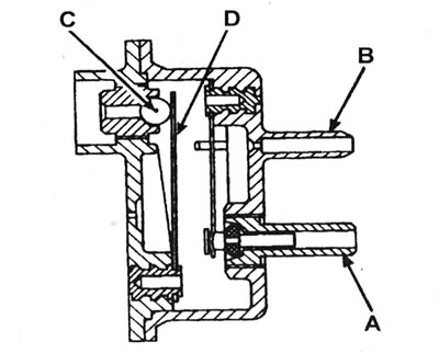
5. This system is distinguished by the fact that the position of the valve is determined not only by temperature, but also by the vacuum in the intake manifold. The combined thermostat and vacuum capsule unit in the air filter inlet duct closes the cold air duct at temperatures below -10°C and closes the hot air duct at temperatures above +20°C. However, at high vacuum in the manifold (more than 200 mbar) the cold air duct will be closed again at temperatures up to 35°C. At temperatures above 35°C, the vacuum supply to the capsule is interrupted by a thermostat valve installed in the air intake cover, and the hot air duct closes (see illustration).


25.5 Schematic diagram of a temperature-controlled vacuum valve: A - To the vacuum capsule; B -…

25.5 Schematic diagram of a temperature-controlled vacuum valve: A - To the vacuum capsule; B - From the intake manifold; C - Valve ball; D - Bimetallic plate.


6. Checking this system is very difficult for a car enthusiast; start by inspecting all vacuum hoses.

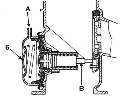
7. The thermostat and vacuum capsule can be checked as described for the central injection system, but to check the operation of the unit at low temperatures, place it in the freezer (see illustration), and to check its operation at high temperatures, warm it up with a hair dryer.
25.7 Thermostat/Vacuum Capsule Schematic (6): A - From the vacuum valve; B - Thermostat.

25.7 Thermostat/Vacuum Capsule Schematic (6): A - From the vacuum valve; B - Thermostat.


8. To check the operation of the thermostat valve, disconnect the hose from the manifold side. Attach a piece of plastic or rubber hose to the valve and create a vacuum in it using a hand pump. When the valve temperature is below 35°C, the vacuum should move the flap, closing the cold air channel. At higher temperatures, the vacuum should have no effect. The movement of the damper cannot be seen with the air filter installed, but it can be heard.
This article is available on: russian, bulgarian, belarusian, ukrainian, serbian, croatian, romanian, polish, slovak, hungarian
Article has been reviewed by editor: Fedoseev Denis
Share with friends:
Previous
Clio 1: Maintenance
Next

Every 20,000 km — test drive
Every 20,000 km — check high-tension wires, distributor cap and rotor
Every 20,000 km — Replace the air filter element
Every 10,000 km or 6 months — check the heating and air conditioning…
Every 10,000 km or 6 months — check the tightness of the wheel bolts
Every 58,000 km — Replace the fuel filter
Every 58,000 km — Replace transmission fluid and filter
Every 58,000 km — Check the rear brake shoe and drum
Every 58,000 km — check the handbrake adjustment
Every 58,000 km — Brake fluid change
Other articles on other Renault models

➽ General description of the air temperature control system… Renault Megane 1 (1995-2002)
➽ Parking control system Renault Duster 1 (2009-2017)
➽ Stability control system ESP with understeer control and… Renault Fluence 1 (2009-2020, petrol)
➽ Oil vapor recovery system — check Renault Kangoo 1 (1997-2007)
➽ Simple remote control without hands-free system Renault Laguna 2 (2001-2007)
Link to this article in different formats
Reviews and comments of visitors
No comments yet


Add two numbers 44 + 22


Clio 1 (1990-1998) 
  • General information
  • Maintenance
  • Troubleshooting
  • Power unit
  • Petrol engines 1.1 l (C)
  • Petrol engines 1.2 l (D)
  • Petrol engines 1.2/1.4 l (E)
  • Petrol engines 1.8 l (F)
  • Diesel engines
  • Overhaul of engines
  • Cooling and heating
  • Fuel system (carburetor)
  • Central fuel injection
  • Distributed fuel injection
  • Fuel system (diesel)
  • Starting and charging system
  • Ignition system (transistor)
  • Ignition system (electronic)
  • Pre-heating of diesel engines
  • Transmission
  • Clutch
  • Manual gearbox
  • Automatic gearbox
  • Drive shafts
  • Chassis, running gear
  • Brake system
  • Car suspension
  • Steering system
  • Body and interior
  • Exterior (external elements)
  • Doors, locks and windows
  • Electrical equipment
  • Equipment and devices
  • Electrical circuits
RenaultBook.ru © 2018–2026 | Mobile version | News and articles | Sitemap: EN BG BY UA RS HR RO PL SK HU | Administration | Site search | Bookmark
Duster 1 (2009-2017) | Fluence 1 (2009-2020, petrol) | Kangoo 1 (1997-2007) | Laguna 2 (2001-2007) | Logan 1 (2004-2012, petrol) | Logan 2 (2012-2020) | Megane 1 (1995-2002) | Megan 2 (2002-2009, petrol) | Sandero 1 (2007-2012, petrol) | Scenic 1 (1996-2003) | Symbol 1 (1999-2008, petrol) | Symbol 2 (2008-2013, petrol) | Renault 19 (1988-1996) | Espace I and II (1984-1996) | Espace III (1996-2002) | Clio 1 (1990-1998) |
We want your visit to be comfortable 😌 and use cookies 🍪 to do so.