



- disconnect the negative battery cable;
- set the front wheels to the straight-ahead position;
- remove the steering wheel and steering column pads (see section "Steering");
- remove the instrument cluster visor;
- remove the instrument cluster;
- remove the antenna ring of the electronic engine start immobilizer system;
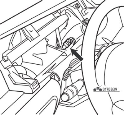
Fig. 8.39. Ignition switch (lock) contact connector
- disconnect the ignition switch connector (Fig. 8.39), releasing the wiring from under the steering column. Remember the order of wiring;
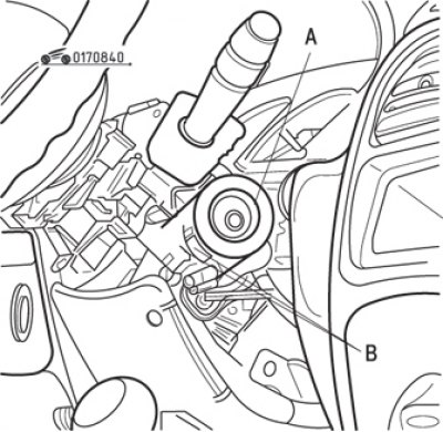
Fig. 8.40. Screw (A) for fixing the ignition switch (lock) and two retaining tabs (B)
- remove the TORX screw at the top of the ignition switch (Fig. 8.40);
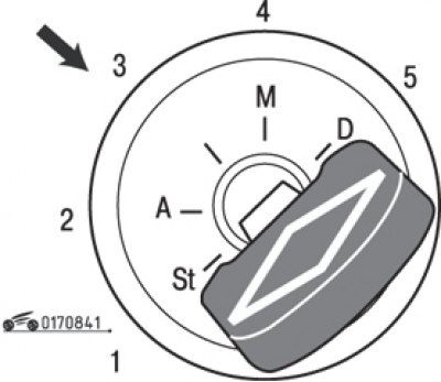
Fig. 8.41. Setting the key in the ignition switch to position "3"
- set the key in the ignition switch to position "3" (Fig. 8.41) and remove the ignition switch by pressing on the retaining tabs B (see fig. 8.40);
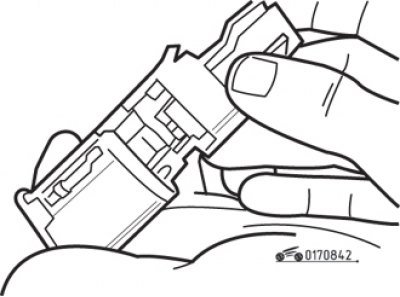
Fig. 8.42. Removing the rear cover from the ignition switch (lock)
- to disconnect the contact group from the ignition switch, unscrew the two screws at the rear of the switch housing and remove the cover (Fig. 8.42).
Install in the reverse order of removal. Route the ignition switch wiring correctly.