



To replace the cylinder head gasket for K7J and K7M engines, do the following.
You will need: the same tools as for removing the timing belt, camshaft pulley (see "Replacement and adjustment of belt tension, replacement of the timing drive tension roller"), cylinder head covers (see "Replacing the cylinder head cover gasket"), as well as a 13 mm wrench, a TORX E14 socket head, a torque wrench, and pliers.
1. Reduce the pressure in the fuel system (see "Reducing pressure in the fuel system").
2. Disconnect the wire from the negative terminal of the battery.
3. Drain the fluid from the engine cooling system (see "Replacing the coolant").
4. Remove the timing belt from the camshaft pulley (see "Replacement and adjustment of belt tension, replacement of the timing drive tension roller").
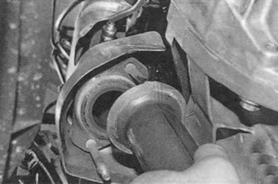
5. Disconnect the inlet pipe from the exhaust manifold (see "Replacement of exhaust system components").
6. Remove the air filter (see "Removal and installation the air filter").
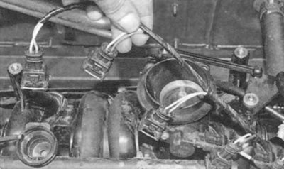
7. After pressing the clamps, disconnect the wiring harness blocks from the injectors...
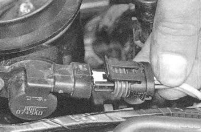
8. ... throttle position sensor...
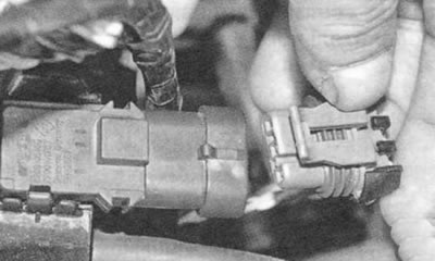
9. ...absolute pressure sensor...
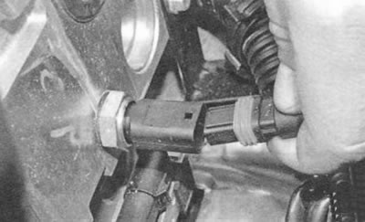
10. ... coolant temperature sensor...
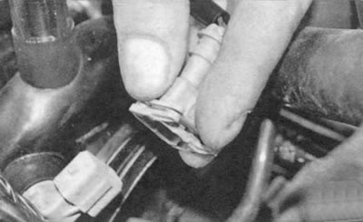
11. ...intake air temperature sensor...
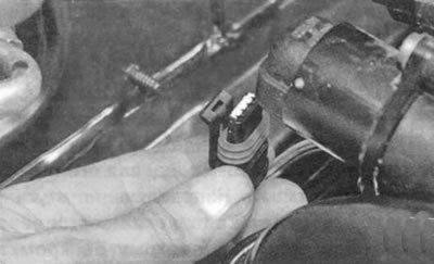
12. ... and idle speed control.
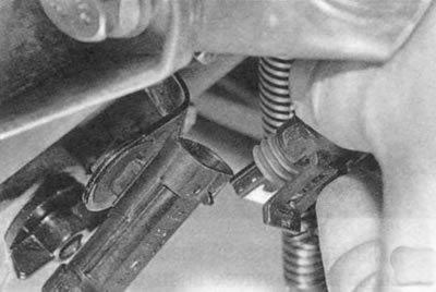
13. Disconnect the oxygen concentration sensor wiring harness connector...
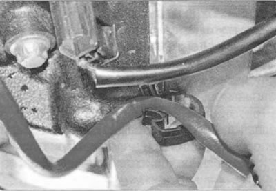
14. ...and remove the harness from the holder on the engine.
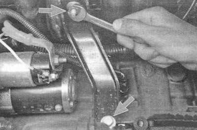
15. On the side of the engine facing the front shield, unscrew the nut securing the spacer to the intake pipe, unscrew the bolt securing it to the cylinder block...
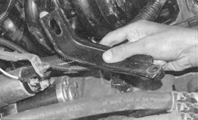
16. ...and remove the spacer.
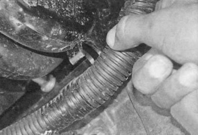
17. Remove the engine harness from the holders on the intake pipe at the rear...
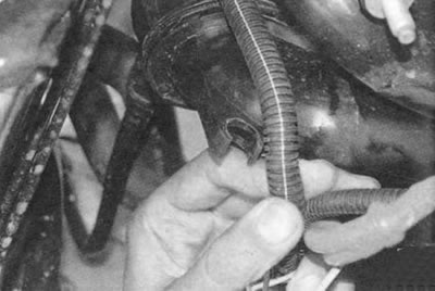
18. ...and in front.
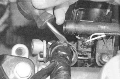
19. Using a screwdriver, unfasten the upper holders of the engine harness at the front...
[Original of this article on the website: RENAULTBOOK.ru]
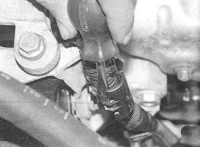
20. ...and behind...
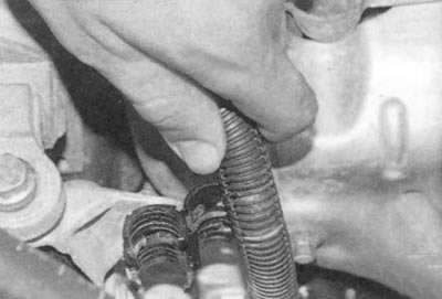
21. ... remove the harness from the front...
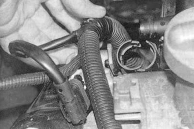
22. ...and rear holders.
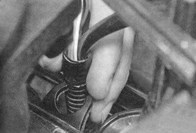
23. Remove the harness from the middle upper holder on the intake pipe...
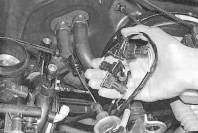
24. ...and take him aside.
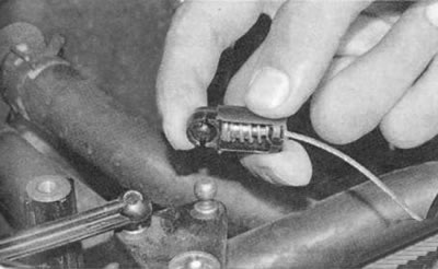
25. Remove the throttle cable end from the intermediate lever ball joint...
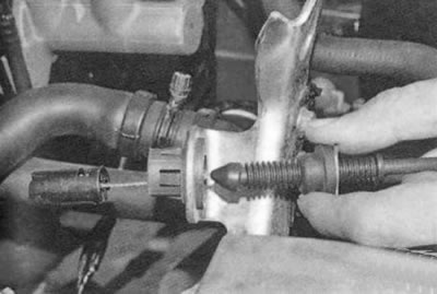
26. ... remove the cable from the bracket hole and move it to the side.
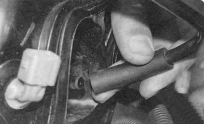
27. Disconnect the purge hose from the canister from the intake pipe.
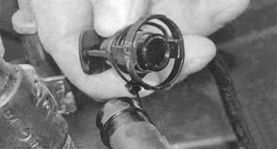
28. Disconnect the fuel line from the fuel rail (see "Removal and installation the fuel rail").
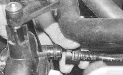
29. Disconnect the hose from the intake pipe to the brake booster by squeezing the clamps that secure it.
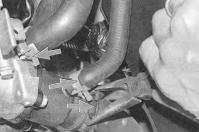
30. Loosen the clamps securing the three hoses by squeezing their bent tabs with pliers, slide the clamps along the hoses...
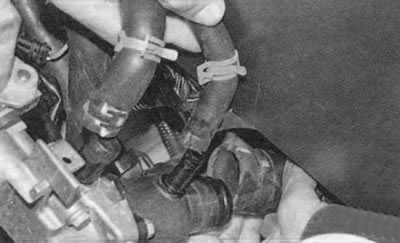
31. ...and disconnect the hoses from the thermostat and cylinder head pipes.
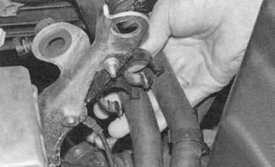
32. Remove the heater hoses from the holders on the bracket.
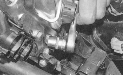
33. Unscrew the bolt securing the ground wire...
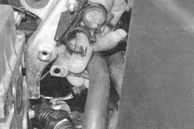
34. ...and disconnect the wire.
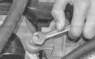
35. Remove the bolt securing the power steering pump bracket to the cylinder head.
36. Remove the cylinder head cover (see "Replacing the cylinder head cover gasket").
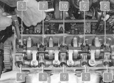
37. Loosen the ten cylinder head mounting bolts in the order shown...
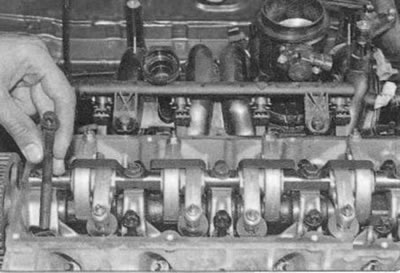
38. ...finally unscrew the head mounting bolts, remove them...
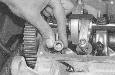
39. ...and remove the washers installed under the bolts.
Warning.
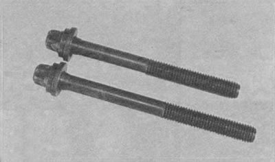
Be sure to replace the cylinder head mounting bolts with new ones. Reuse is not allowed. Note that the bolts are of different lengths. When removing them, remember the location of the bolts and then install them in their original places.
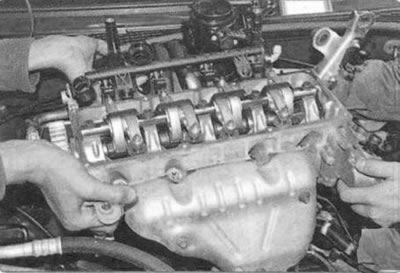
40. Remove the cylinder head assembly with the intake pipe, throttle body and exhaust manifold...
Helpful advice: It is easier to remove the cylinder head with an assistant, as it is quite heavy.
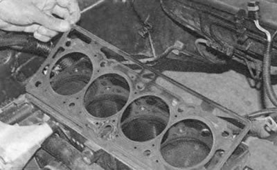
41. ...then remove its gasket.
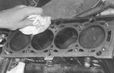
42. Clean the mating surfaces of the head and block.
43. Check the cylinder head for warpage. To do this, place a ruler on its edge on the surface of the head, first in the middle along, then across, and also diagonally, and use a feeler gauge to measure the gap between the plane of the head and the ruler. Replace the cylinder head if the gap is more than 0.05 mm.
44. Install the cylinder head in the reverse order of removal, taking into account the following:
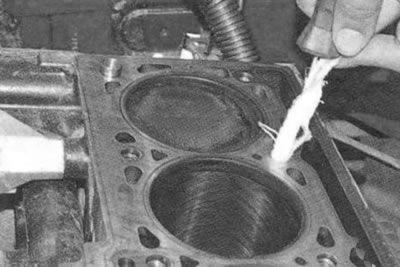
- remove any oil or coolant from the threaded holes of the cylinder head mounting bolts that got there when removing the head;
- be sure to install a new cylinder head gasket, reusing the gasket is not allowed;
- replace the bolts with new ones;
- lubricate the bolts with engine oil;
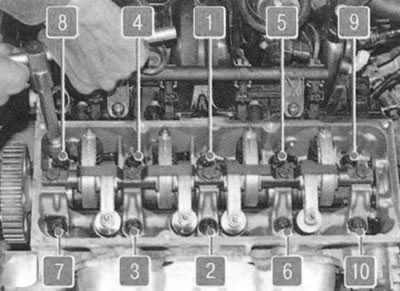
- tighten the bolts on a cold engine in the following order in four stages:
Stage I (preliminary settling of the gasket) - tighten the bolts to a torque of 20 N·m (2 kgf·m), then turn them further to an angle of 100°±6°. Wait 3 min;
Stage II - loosen bolts 1 and 2, then tighten them again to a torque of 20 Nm (2 kgf·m) and turn them further to an angle of 110°±6°;
Stage III - loosen bolts 3, 4, 5 and 6, then tighten them again to a torque of 20 Nm (2 kgf·m) and turn them further to an angle of 110°±6°;
Stage IV - loosen bolts 7, 8, 9 and 10, then tighten them again to a torque of 20 Nm (2 kgf·m) and turn them further to an angle of 110°±6°.
45. Install all removed parts and assemblies, except for the cylinder head cover and air filter, in the reverse order of removal.
46. Adjust the timing belt tension (see "Replacement and adjustment of belt tension, replacement of the timing drive tension roller") and the accessory drive belt (see "Checking the tension of the auxiliary drive belt").
47. Check and, if necessary, adjust the valve drive clearances (see "Adjusting valve clearances").
48. Install the cylinder head cover (see "Replacing the cylinder head cover gasket").
49. Install the air filter (see "Removal and installation the air filter").
50. Fill with coolant (see "Replacing the coolant").
To replace the cylinder head gasket of the K4M engine, do the following.
You will need: the same tools as for removing the timing belt, camshaft pulleys (see "Replacement and adjustment of belt tension, replacement of the timing drive tension roller"), cylinder head covers (see "Replacing the cylinder head cover gasket"), as well as a 13 mm wrench, a TORX E14 socket head, a torque wrench, and pliers.
1. Reduce the pressure in the fuel system (see "Reducing pressure in the fuel system").
2. Disconnect the wire from the negative terminal of the battery.
3. Drain the fluid from the engine cooling system (see "Replacing the coolant").
4. Remove the timing belt (see "Replacement and adjustment of belt tension, replacement of the timing drive tension roller").
5. Disconnect the inlet pipe from the exhaust manifold (see "Replacement of exhaust system components").
6. Disconnect the wiring harness connectors:
- from injectors;
- throttle position sensors, absolute pressure, coolant temperature, intake air temperature, oxygen concentration;
- idle speed controller;
- ignition coils.
Note: The operations listed in paragraph 6 are described in section. "Electrical equipment".
7. Remove the air filter (see "Removal and installation the air filter").
8. Remove the engine wiring harness from the holders on the engine and set it aside.
9. Remove the ignition coils (see "Checking. Removing and installing ignition coils of the K4M engine").
10. Disconnect the throttle cable from the throttle assembly (see "Replacing the throttle cable")...
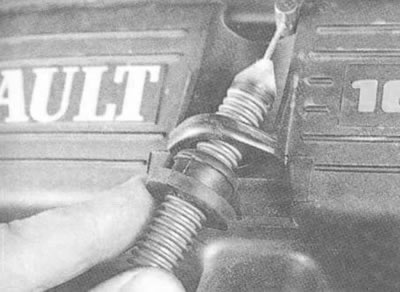
11. ... remove the cable from the receiver bracket and move it to the side.
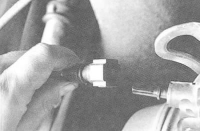
12. Disconnect the purge hose from the canister from the intake pipe.
13. Disconnect the fuel line from the fuel rail (see "Removal and installation the fuel rail").
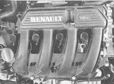
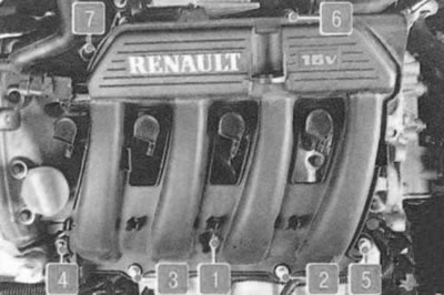
14. Remove the seven bolts securing the receiver to the cylinder head cover...
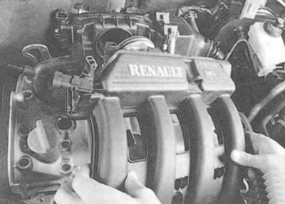
15. ...and remove the receiver.
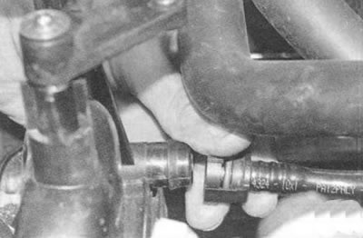
16. Disconnect the hose from the intake pipe to the brake booster by squeezing the clamps that secure it.
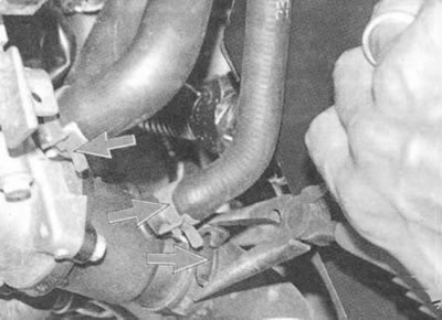
17. Loosen the clamps securing the three hoses by squeezing their bent tabs with pliers, slide the clamps along the hoses...
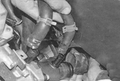
18. ...and disconnect the hoses from the thermostat and cylinder head pipes.
19. Remove the power steering pump mounting bolts and move the pump to the side (see "Replacing the power steering pump").
20. Remove the fuel rail protection (see "Removal and installation the fuel rail").
21. Remove the cylinder head cover (see "Replacing the cylinder head cover gasket").
22. Remove the camshafts (see "Replacing the camshaft").
23. Using a TORX E14 socket head, unscrew the ten cylinder head mounting bolts and remove the bolts (Fig. 5.9).
Warning.
Be sure to replace the cylinder head mounting bolts with new ones. Reusing them is not allowed. Note that the bolts are of different lengths. When removing them, remember the location of the bolts and then install them in their original places.
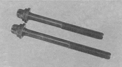
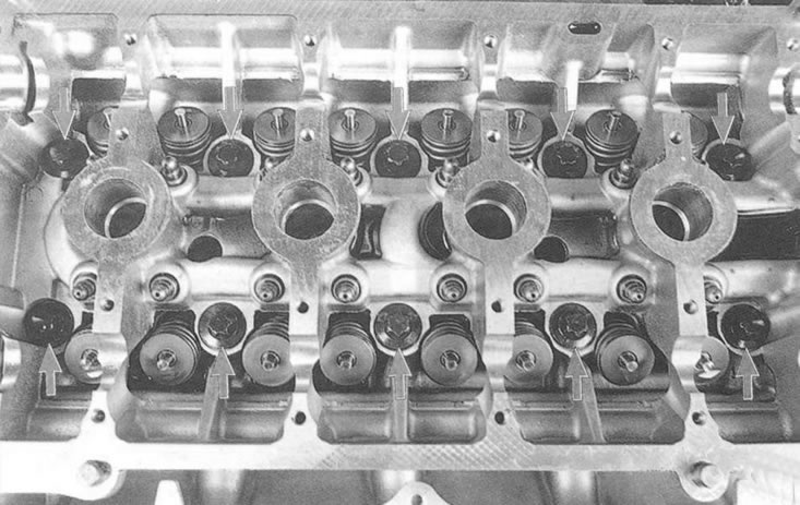
Fig. 5.9. Cylinder head mounting bolts.
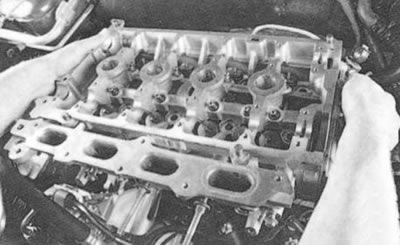
24. Remove the cylinder head assembly with the exhaust manifold.
Helpful advice: It is easier to remove the cylinder head with an assistant, as it is quite heavy.
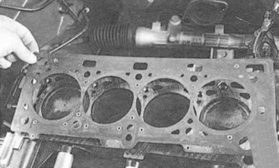
25. Remove the gasket.
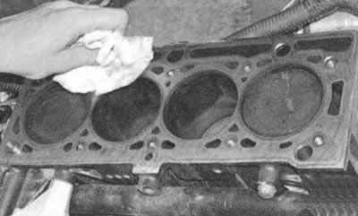
26. Clean the mating surfaces of the head and block.
27. Check the cylinder head for warpage. To do this, place a ruler on its edge on the surface of the head, first in the middle lengthwise, then across, and also diagonally, and use a feeler gauge to measure the gap between the surface of the head and the ruler. Replace the cylinder head if the gap is more than 0.05 mm.
28. Install the cylinder head in the reverse order of removal, taking into account the following:
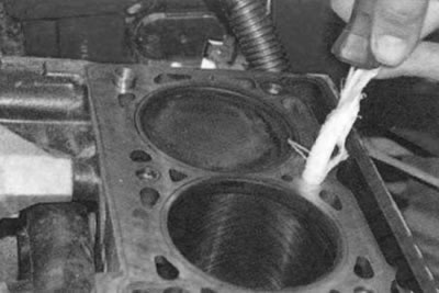
- remove any oil or coolant from the threaded holes of the cylinder head mounting bolts that got there when removing the head;
- be sure to install a new cylinder head gasket, reusing the gasket is not allowed;
- replace the bolts with new ones;
- lubricate the bolts with engine oil;
- tighten the bolts on a cold engine in the order shown (Fig. 5.10) in two stages:
Stage I (preliminary settling of the gasket) - tighten the bolts to a torque of 20 Nm (2 kgf·m);
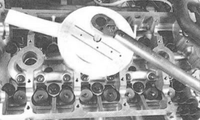
Stage II - tighten the bolts to an angle of 240°±6°.
Note.
The photo shows an example of tightening the cylinder head bolt to a certain angle.
29. Install all removed parts and assemblies in the reverse order of removal.
Note.
When installing the receiver, tighten the mounting bolts to a torque of 9 N·m (the tightening sequence is shown in the photo).
30. Adjust the timing belt tension (see "Replacement and adjustment of belt tension, replacement of the timing drive tension roller") and the auxiliary drive belt (see "Checking the tension of the auxiliary drive belt").
31. Fill with coolant (see "Replacing the coolant").
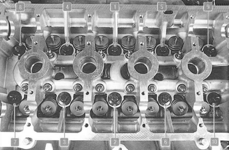
Fig. 5.10. Cylinder head bolt tightening sequence.