



Note: Adjustment of valve clearances is required for K7J and K7M engines.
The K4M engine uses hydraulic compensators, which automatically ensure gap-free contact of the camshaft cam with the valve.
The need to adjust the clearances in the valve drive is indicated by a distinct loud knock, audible when the engine is idling from the driver's seat with the hood closed. Increased clearances do not lead to emergency engine failures, but cause increased wear of the valve mechanism parts. In addition, with increased clearances of the intake valves, the filling of the cylinders with a combustible mixture is worsened and, as a result, the engine power decreases. With a complete absence of clearances in the exhaust valves, in addition to uneven operation and a decrease in engine power due to reduced compression in the cylinders, it is possible that the plates of these valves and their seats will burn out due to overheating, since a valve that does not fit tightly into the seat is poorly cooled.
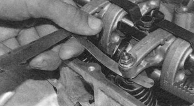
The clearance is measured on a cold engine (at a temperature of +20°C) between the ends of the valve stem and the adjusting bolt with the valve completely closed. The nominal clearance for intake valves is 0.10-0.15 mm, for exhaust valves - 0.25-0.30 mm.
Before starting the adjustment, be sure to check and, if necessary, adjust the tension of the timing belt (see "Replacement and adjustment of belt tension, replacement of the timing drive tension roller").
You will need: all the tools necessary to remove the cylinder head cover, as well as a 10 mm spanner, pliers, and a set of flat feeler gauges.
1. Remove the cylinder head cover (see "Replacing the cylinder head cover gasket").
2. Set the piston of the 1st cylinder to the TDC position of the compression stroke (see "Setting the piston of the first cylinder to the TDC position of the stroke"). In this position, both valves of the 1st cylinder will be closed and the gaps between the ends of the valves and the adjusting bolts will be maximum.
Note: Cylinders are counted from the flywheel.
Helpful Hint: To set the piston of the 1st cylinder to the TDC position of the compression stroke, it is necessary to remove the upper cover of the timing belt (to gain access to the timing marks on the camshaft pulley and on the cylinder head cover), which entails labor-intensive preliminary operations to remove the right support of the power unit suspension. With sufficient accuracy to adjust the clearances in the valve mechanism, the camshaft can be set to the desired position, checking it visually. The camshaft must be turned so that the heels of the rocker arms of the drive of both valves of the cylinder, which is being adjusted, rest on the back of the cams of the camshaft, and the rocker arms can be moved by "rocking" within the gap.
View the original source on this resource Renaultbook.ru
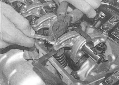
3. Loosen the lock nut of the adjusting bolt of one of the rocker arms, holding the bolt from turning with pliers. Insert a feeler gauge into the gap between the ends of the valve and the adjusting bolt.
4. While holding the lock nut from turning, turn the adjusting bolt clockwise until the feeler gauge in the gap can be moved with slight force.
Warning: Do not screw in the adjusting bolt until the feeler gauge is completely pinched, as this will cause the valve to move and the clearance will be obviously less than the norm.
5. While holding the adjusting bolt from turning, tighten the lock nut and check the clearance. Repeat the adjustment if necessary.
6. Adjust the clearance for the second valve in the same way.
7. Turn the crankshaft exactly half a turn. With this position of the crankshaft, both valves of the 3rd cylinder are completely closed and their rocker arms are released.
8. Adjust the clearances between the ends of the valves and the adjusting screws of the 3rd cylinder.
9. By subsequent turns of the crankshaft exactly half a turn, set the pistons of the 4th, and then the 2nd cylinder to TDC of the compression stroke and adjust the clearances for the remaining valves.
10. Install the cylinder head cover and all removed parts in the reverse order of removal. If necessary, replace a tightly compressed cover gasket.