English Русский
Български
Беларускі
Український
Српски
Hrvatski
Română
Polski
Slovenský
Magyar
Bookmark Contacts Articles Sitemap
Company vehicles Peugeot Company vehicles Opel Company vehicles Skoda Company vehicles Land Rover Company vehicles Mitsubishi Company vehicles Volkswagen Company vehicles Honda
RenaultBook.ru


Duster   Fluence   Kangoo   Laguna   Logan   Megane   Sandero   Scenic   Symbol   Clio   Other
Sandero 1 (2007-2012, petrol)

Setting the piston of the first cylinder to the TDC position of the compression stroke (Renault Sandero 1)

  • Main
  • Sandero
  • Sandero 1 (2007-2012, petrol)
  • Power unit
  • Engine repair
  • Setting the piston of the first cylinder to the TDC position of the compression stroke
0
The piston of the 1st cylinder is set to the TDC position (top dead center) compression stroke so that the valve timing is not disturbed when performing work related to removing the camshaft drive belt. If the valve timing is disturbed, the engine will not operate normally.

Note: On Renault engines, unlike on engines of most brands of cars, the cylinder count is based on the flywheel, not the crankshaft pulley.


To set the piston of the first cylinder of the K7J and K7M engines to the TDC position of the compression stroke, do the following.

Set the TDC according to the mark on the camshaft pulley (when installed according to the marks on the crankshaft pulley, the piston of either the 1st or 4th cylinder may be in this position). After this, be sure to check that the marks on the toothed pulley of the crankshaft match (with the auxiliary drive pulley removed). If the marks on the crankshaft pulley do not match, then the valve timing is out of alignment (piston of the 1st cylinder is not set to TDC). In this case, it is necessary to remove the camshaft drive belt and turn the crankshaft until the marks are aligned.

Helpful advice. The crankshaft is turned to check the coincidence of the marks for the bolt that attaches the auxiliary drive pulley to it, having removed the upper part of the right engine mudguard to access it. In addition, this can be done in the following ways (especially when adjusting valve clearances, when control by marks on the toothed pulley of the crankshaft is not necessary):
  • 1) engage any gear (preferably IV) and slowly roll the car until the marks align;
  • 2) lift one front wheel, engage any gear and then turn the lifted wheel until the marks align.

2) lift one front wheel, engage any gear and then turn the lifted wheel until the marks align.


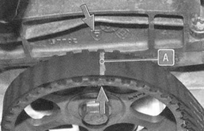
The mark on the camshaft toothed pulley must be aligned with the mark on the cylinder head cover, which is made in the form of the Dachia logo...


Note: In addition to the marks on the pulley, the timing belt has a painted line A, which must also be aligned with the mark on the pulley when setting the valve timing.

Note: In addition to the marks on the pulley, the timing belt has a painted line A, which must also…


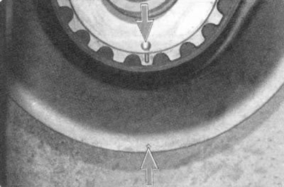
...and the mark on the toothed pulley of the crankshaft must be aligned with the mark on the cylinder block. It becomes visible after removing the accessory drive pulley. The risk and the round protrusion on the toothed pulley must coincide with the hole on the cylinder block.

You will need: socket wrenches (heads) "10", "18".

1. Remove the right front wheel.

Warning: Loosen the wheel bolts only when the vehicle is on the ground. If you are working on a ditch or overpass, block the wheels, apply the parking brake, and support the front of the vehicle securely.


2. Remove the upper part of the right engine splash guard (see "Removal and installation mudguards and engine crankcase protection").

3. Remove the accessory drive belt (see "Replacement of auxiliary drive belts").

4. Remove the right powertrain suspension support (see "Replacing the right powertrain suspension support").
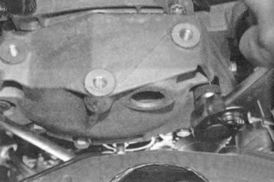
4. Remove the right powertrain suspension support (see «Replacing the right powertrain suspension…


5. Remove the five bolts securing the upper timing belt cover...
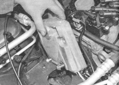


5. Remove the five bolts securing the upper timing belt cover...


6. ...and remove the lid.
6. ...and remove the lid.


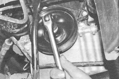
7. Turn the crankshaft clockwise by the accessory drive pulley mounting bolt until the marks on the camshaft pulley and cylinder head cover align. Then loosen the tightening...
7. Turn the crankshaft clockwise by the accessory drive pulley mounting bolt until the marks on the…


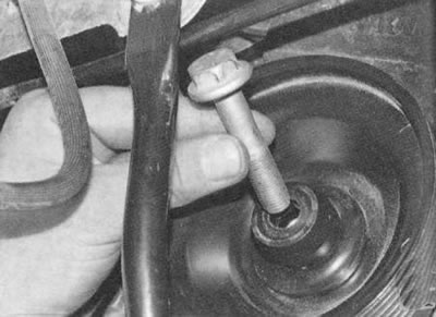
8. ...finally unscrew the pulley mounting bolt...
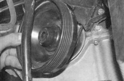
8. ...finally unscrew the pulley mounting bolt...


9. ...and remove the pulley.
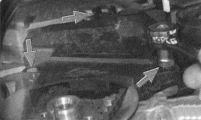


9. ...and remove the pulley.


10. Remove the three bolts securing the lower timing belt cover...
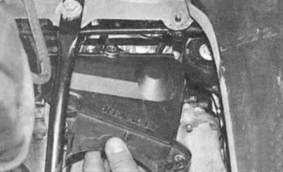
10. Remove the three bolts securing the lower timing belt cover...


11. ...and remove the cover.

Note: It is not necessary to remove the lower cover beforehand when checking the valve timing. This may be necessary if a phase misalignment is detected and it is necessary to restore the installation by loosening the timing belt tension.
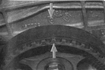

Note: It is not necessary to remove the lower cover beforehand when checking the valve timing. This…


12. Check the alignment of the marks on the camshaft toothed pulley and on the cylinder head cover.


To set the piston of the 1st cylinder of the K4M engine to the TDC position of the compression stroke, do the following.

You will need: a 15 mm, 18 mm socket head, a 13 mm wrench, a flat-blade screwdriver, a TORX E14 wrench...
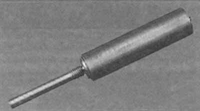
You will need: a 15 mm, 18 mm socket head, a 13 mm wrench, a flat-blade screwdriver, a TORX E14…


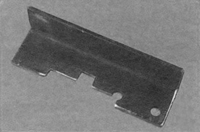
... TDC setting tool...

... TDC setting tool...


... and a camshaft locking tool.

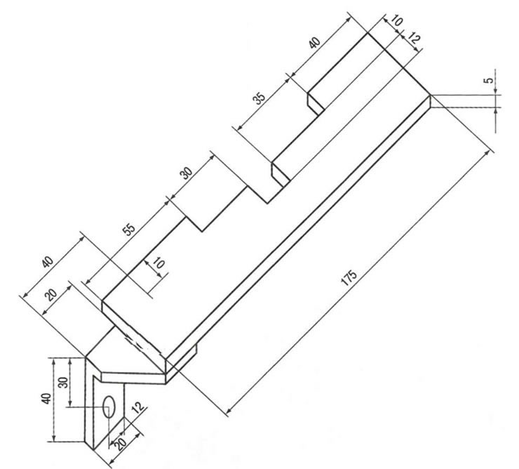
Note: If special fasteners are not available, they can be made using the sketches shown in Fig. 5.6 and 5.7.
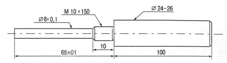

Note: If special fasteners are not available, they can be made using the sketches shown in Fig. 5.6…

Fig. 5.6. TDC position lock.


Fig. 5.6. TDC position lock.

Fig. 5.7. Camshaft locking tool.

1. Remove the right front wheel.

2. Remove the upper part of the right engine splash guard (see "Removal and installation mudguards and engine crankcase protection").

3. Remove the accessory drive belt (see "Replacement of auxiliary drive belts").

4. Remove the right powertrain suspension support (see "Replacing the right powertrain suspension support").
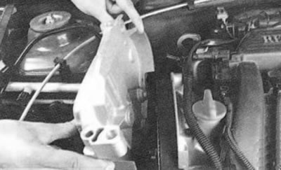
4. Remove the right powertrain suspension support (see «Replacing the right powertrain suspension…


5. Remove the upper timing belt cover (see "Replacement and adjustment of belt tension, replacement of the timing drive tension roller").
5. Remove the upper timing belt cover (see «Replacement and adjustment of belt tension, replacement…


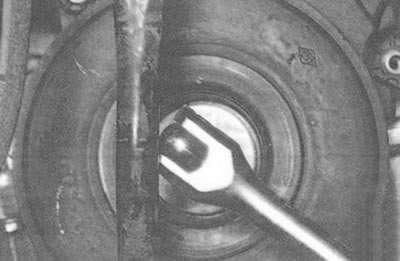
6. Rotate the crankshaft clockwise using the auxiliary drive pulley mounting bolt...
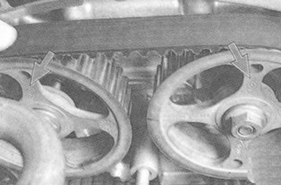


6. Rotate the crankshaft clockwise using the auxiliary drive pulley mounting bolt...


7. ...set the marks on the camshaft pulleys with the Renault logo so that they are slightly below the top point.
7. ...set the marks on the camshaft pulleys with the Renault logo so that they are slightly below…


View the original source on this resource [www.renaultbook.ru]

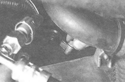
8. Use a TORX E14 key to unscrew the plug of the hole for installing the TDC position lock.

Note: The plug is located to the left of the flywheel in the cylinder block at the level of the 1st cylinder.
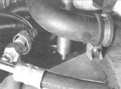
Note: The plug is located to the left of the flywheel in the cylinder block at the level of the 1st…


9. Screw the TDC position lock into the hole.


10. Turn the engine crankshaft until it stops.
10. Turn the engine crankshaft until it stops.


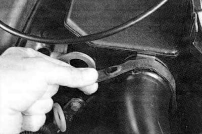
11. Unfasten the rubber clamp securing the air supply hose.
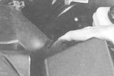
11. Unfasten the rubber clamp securing the air supply hose.


12. Disconnect the air supply hose from the air filter housing...
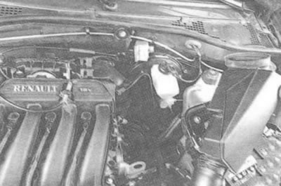
12. Disconnect the air supply hose from the air filter housing...


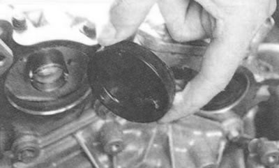
13. ...and remove the sleeve.
13. ...and remove the sleeve.


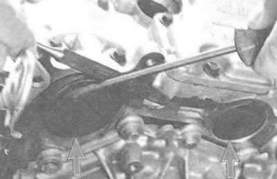
14. Using a flat-blade screwdriver...
14. Using a flat-blade screwdriver...


15. ...press out the camshaft plugs from the rear of the cylinder head.

Notes:
  • For clarity, shown with the receiver removed.
  • Replace the camshaft plugs with new ones during assembly.
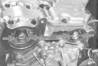

Replace the camshaft plugs with new ones during assembly.


16. When the piston of the 1st cylinder is correctly installed in the TDC position of the compression stroke, the grooves on the ends of the camshafts should be horizontal and shifted downwards relative to the axis of the camshafts.
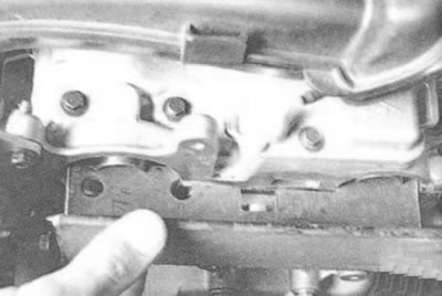
16. When the piston of the 1st cylinder is correctly installed in the TDC position of the…


17. Lock the camshafts in this position with the camshaft locking tool.
This article is available on: russian, bulgarian, belarusian, ukrainian, serbian, croatian, romanian, polish, slovak, hungarian
Article has been reviewed by editor: Podkrepilov Maxim
Share with friends:
Previous
Sandero 1: Engine repair
Next

Cleaning the crankcase ventilation system
Replacing the powertrain suspension mounts
Removal and installation mudguards and engine crankcase protection
Checking the compression in the cylinders
Engine — design features
Replacement and adjustment of belt tension, replacement of the timing…
Adjusting valve clearances
Checking, flushing and replacing hydraulic compensators for…
Removal, defect detection and installation of the flywheel
Replacing the cylinder head cover gasket
Other articles on other Renault models

➽ Setting the piston of the first cylinder to the TDC position of… Renault Logan 1 (2004-2012, petrol)
➽ Compression Stroke End Pressure — Check Renault Duster 1 (2009-2017)
➽ Installation of cylinder injectors and piston bottom cooling for… Renault Fluence 1 (2009-2020, petrol)
➽ Setting the position of the pistons in relation to the… Renault Megan 2 (2002-2009, petrol)
➽ Installing the piston group into the cylinder block Renault Symbol 1 (1999-2008, petrol)
Link to this article in different formats
Reviews and comments of visitors
No comments yet


Add two numbers 20 + 33


Sandero 1 (2007-2012, petrol) 
  • General information
  • Structure of car
  • User manual
  • Troubleshooting
  • Maintenance
  • Practical advice
  • Power unit
  • Engine repair
  • Lubrication system
  • Cooling system
  • Fuel and exhaust system
  • Transmission
  • Clutch
  • Manual gearbox
  • Automatic gearbox
  • Drive shafts
  • Chassis, running gear
  • Front suspension
  • Rear suspension
  • Steering
  • Brake system
  • Wheels and tires
  • Body and interior
  • Exterior (external elements)
  • Interior (internal elements)
  • Doors, locks and windows
  • Car body care
  • Heater and air conditioner
  • Security system
  • Electrical equipment
  • Equipment and devices
  • Headlights and lighting
  • Power devices
  • Ignition system
  • Electrical diagrams
RenaultBook.ru © 2018–2026 | Mobile version | News and articles | Sitemap: EN BG BY UA RS HR RO PL SK HU | Administration | Site search | Bookmark
Duster 1 (2009-2017) | Fluence 1 (2009-2020, petrol) | Kangoo 1 (1997-2007) | Laguna 2 (2001-2007) | Logan 1 (2004-2012, petrol) | Logan 2 (2012-2020) | Megane 1 (1995-2002) | Megan 2 (2002-2009, petrol) | Sandero 1 (2007-2012, petrol) | Scenic 1 (1996-2003) | Symbol 1 (1999-2008, petrol) | Symbol 2 (2008-2013, petrol) | Renault 19 (1988-1996) | Espace I and II (1984-1996) | Espace III (1996-2002) | Clio 1 (1990-1998) |
We want your visit to be comfortable 😌 and use cookies 🍪 to do so.