



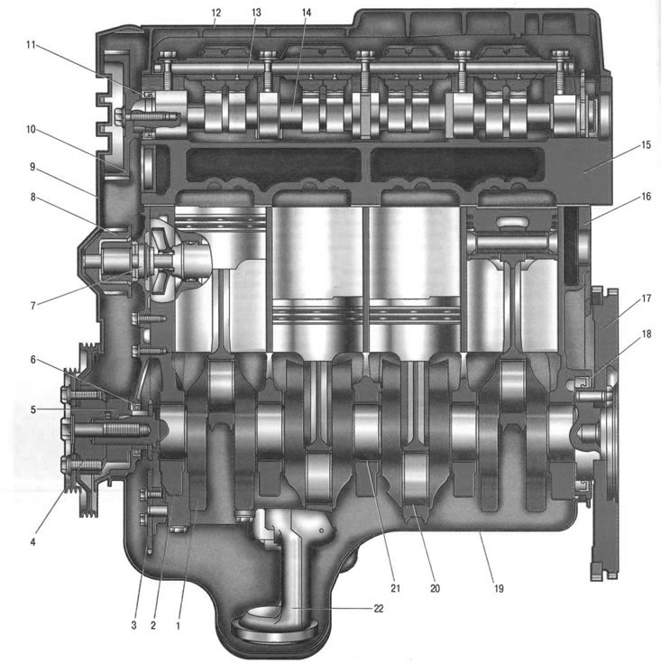
Fig. 5.1. Engine K7J or K7M (longitudinal section): 1 - crankshaft; 2 - crankshaft main bearing cap; 3 - oil pump sprocket; 4 - auxiliary drive pulley; 5 - toothed pulley of the crankshaft; 6 - front crankshaft oil seal; 7 - water pump; 8 - toothed pulley of water pump; 9 - valve timing belt cover; 10 - camshaft toothed pulley; 11 - camshaft oil seal; 12 - cylinder head cover; 13 - valve drive rocker arm axis; 14 - camshaft; 15 - cylinder head; 16 - cylinder block; 17 - flywheel; 18 - rear crankshaft oil seal; 19 - oil pan; 20 - connecting rod bearing shell; 21 - main bearing shell; 22 - oil pump inlet pipe
Note. The operation of a piston internal combustion engine is based on the use of the work of thermal expansion of heated gases during the movement of the piston from top dead center (TDC) to bottom dead center (BDC). Heating of gases at TDC is achieved as a result of combustion of fuel mixed with air in the cylinder. This increases the temperature of the gases and the pressure. Since the pressure under the piston is equal to atmospheric pressure, and in the cylinder it is much greater, the piston will move downwards under the action of the pressure difference, and the gases will expand, performing useful work. In order for the engine to constantly generate mechanical energy, a mixture of air and fuel must be periodically supplied to the cylinder through the intake valve. The combustion products of the fuel after their expansion are removed from the cylinder through the exhaust valve. These tasks are performed by the valve timing mechanism, which controls the opening and closing of the valves, and the fuel supply system. The working cycle of an engine is a periodically repeating series of sequential processes occurring in each cylinder of the engine and causing the conversion of thermal energy into mechanical work. Automobile engines generally operate on a four-stroke cycle, which is completed in two revolutions of the crankshaft or four strokes of the piston and consists of intake, compression, and expansion strokes (working stroke) and release.
The K7J and K7M engines are almost identical in design, but differ in displacement. Moreover, the displacement of the K7M engine is increased compared to the K7J engine due to the increase in piston stroke, which is achieved by increasing the crankshaft crank radius with the same cylinder diameter. This entailed an increase in the height of the K7M engine cylinder block.
Note: Engine displacement (liter capacity) is one of the most important design parameters (characteristics) internal combustion engine (ICE), expressed in liters (l) or cubic centimeters (cm³).
The engine's working volume largely determines its power and other operating parameters. It is equal to the sum of the working volumes of all engine cylinders. In turn, the working volume of a cylinder is defined as the product of the cross-sectional area of the cylinder and the length of the piston's working stroke (from BDC to TDC). According to this parameter, a distinction is made between long-stroke engines with a piston stroke length exceeding the cylinder diameter, and short-stroke engines with a piston stroke less than the cylinder diameter.
In addition, due to the increased diameter of the clutch, aggregated with the K7M engine, the diameter of the flywheel is also increased, which, in turn, caused a change in the shape of the clutch housing. That is why the location of the threaded holes for fastening the gearbox in the cylinder blocks of these engines is also different. The design of the engines is shown in Fig. 5.1 and 5.2.
The K7J and K7M engines with an overhead camshaft with one five-bearing camshaft have two valves per cylinder. The camshaft of the engines is driven by a reinforced toothed belt. The valves of the K7J and K7M engines are driven from the camshaft by rocker arms, which rest on one shoulder on the camshaft cams and have bolts on the other shoulder for adjusting the clearances in the valve mechanism with locknuts, acting on the ends of the valve stems.
Cylinder head 15 (see fig. 5.1) the engines are made of aluminum alloy with a transverse cylinder scavenging scheme (the inlet and outlet ports are located on opposite sides of the head). The head is pressed with seats and guide bushings 15 (see fig. 5.2) valves. The inlet 7 and outlet 16 valves are each equipped with one spring 14, fixed through a plate 13 by two crackers.
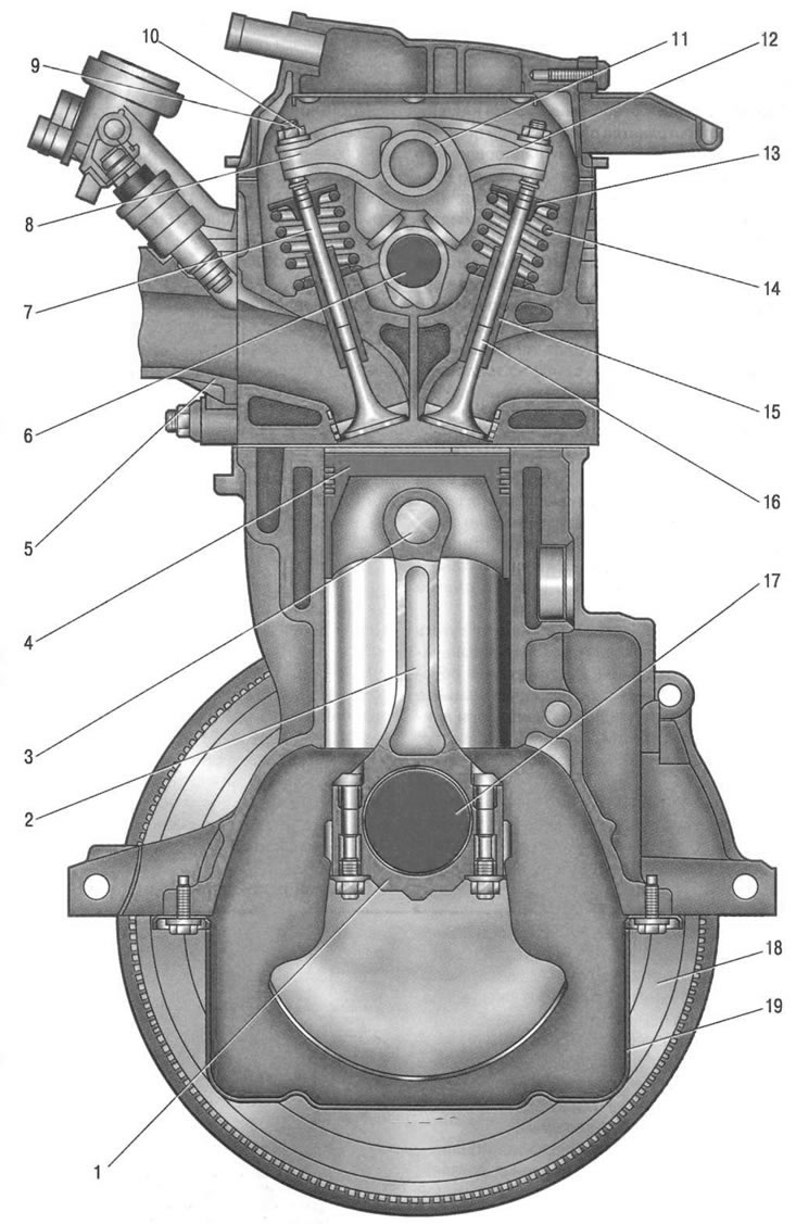
Fig. 5.2. Engine K7J or K7M (cross section): 1 - connecting rod cover; 2 - connecting rod; 3 - piston pin; 4 - piston; 5 - inlet pipe; b - camshaft; 7 - inlet valve; 8 - intake valve rocker; 9 - adjusting bolt; 10 - adjusting bolt lock nut; 11 - valve drive rocker arm axis; 12 - exhaust valve rocker; 13 - valve spring plate; 14 - valve spring; 15 - valve guide bushing; 16 - exhaust valve; 17 - crankshaft; 18 - flywheel; 19 - oil pan
On the upper surface of the K7J and K7M engine block head, the axis 11 of the rocker arms 8 and 12 of the inlet and outlet valves, respectively, is bolted. Bolts 9, secured with locknuts 10, are installed in the holes made in the rocker arms to adjust the clearances in the valve drive mechanism, resting on the ends of the valve stems.
The plane of the joint between the head and the cylinder block is sealed with a gasket, which is a plate molded from thin sheet metal.
Note: Compression ratio is the ratio of the volume of the above-piston space of the cylinder when the piston is at BDC to the volume of the above-piston space of the cylinder when the piston is at TDC, i.e. to the volume of the combustion chamber.
Increasing the compression ratio requires the use of fuel with a higher octane number (for gasoline internal combustion engines) to avoid detonation. Increasing the compression ratio generally increases its power, and also increases the engine efficiency, i.e. helps reduce fuel consumption.
In the 1950s and 1960s, one of the trends in engine building was to increase the compression ratio, which by the early 1970s often reached 11-13:1. However, this required the appropriate gasoline with a high octane number, which in those years could only be obtained by adding poisonous tetraethyl lead (leaded gasoline). The introduction of environmental standards in most countries in the early 1970s led to a halt in the growth and even a reduction in the compression ratio in production engines.
The term "compression ratio" should not be confused with the term "compression", which means (at a certain structurally determined degree of compression) maximum pressure created in the cylinder when the piston moves from BDC to TDC (for example, compression ratio is 10:1, compression is 14 atm).
Camshaft engines 14 (see fig. 5.1) installed in bearing beds made in the head body and fixed against axial movement by thrust flanges.
Cylinder blocks 16 (see Fig. 5. The engines being added are identical and are a single casting that forms the cylinders, cooling jacket, upper part of the crankcase and five crankshaft supports made in the form of crankcase partitions. The cylinder block is made of special high-strength cast iron with cylinders bored directly in the block body. The 2 main bearing caps are machined together with the block and are not interchangeable. The cylinder block has special bosses, flanges and holes for fastening parts, units and assemblies, as well as channels for the main oil line.
Crankshaft 1 rotates in main bearings having thin-walled steel liners 20 and 21 with an antifriction layer. The axial movement of the crankshaft is limited by two thrust half rings installed in the grooves of the bed of the middle main bearing.
Flywheel 17, cast from cast iron, is installed on the rear end of the crankshaft and secured with seven bolts. A toothed rim for starting the engine with a starter is pressed onto the flywheel. In addition to it, a toothed crown is made on the flywheel, ensuring the operation of the top dead center sensor of the engine management system.
Pistons (Fig. 5.3) are made of aluminum alloy. On the cylindrical surface of the piston head there are annular grooves for the oil scraper and two compression rings.
Piston pins 3 (see fig. 5.2) they are installed in the piston bosses with a gap and are pressed with tension into the upper heads of the connecting rods, which are connected with their lower heads to the connecting rod journals of the crankshaft through thin-walled liners, similar in design to the main ones.
Connecting rods2 steel, forged, with I-section rod.
Lubrication system combined (for more details see. "Lubrication system").
Crankcase ventilation system closed type does not communicate directly with the atmosphere, therefore, simultaneously with the suction of gases in the crankcase, a vacuum is formed in all engine operating modes, which increases the reliability of various engine seals and reduces the emission of toxic substances into the atmosphere.
The system consists of two branches, large and small.
When the engine is idling and operating at low loads, when the vacuum in the intake manifold is high, crankcase gases are sucked in by the intake manifold through the small branch of the system.
At full load conditions, when the throttle valve is open at a large angle, the vacuum in the intake pipe decreases, and in the air supply hose it increases, and crankcase gases through the large branch hose connected to the fitting on the cylinder head cover mainly enter the air supply hose, and then through the throttle assembly into the intake pipe and engine cylinders.
Cooling system engines, hermetically sealed, with an expansion tank, consists of a cooling jacket made in casting and surrounding the cylinders in the block, combustion chambers and gas channels in the cylinder head. Forced circulation of the coolant is provided by a centrifugal water pump 7 (see fig. 5.1) with a crankshaft drive by a toothed timing belt. To maintain the normal operating temperature of the coolant, a thermostat is installed in the cooling system, which closes the large circle of the system when the engine is not warmed up and the coolant temperature is low.
Power supply system engines consists of an electric fuel pump installed in the fuel tank, a throttle assembly, a fine fuel filter, a fuel pressure regulator located in the fuel pump module, injectors and fuel lines, and also includes an air filter.
Ignition system engines microprocessor, consists of an ignition module, high-voltage wires and spark plugs. The ignition module is controlled by an electronic unit of the engine management system. The ignition system does not require maintenance or adjustment during operation.
The main difference between the K4M engine (Fig. 5.4) and the K7J and K7M engines is the presence of a cylinder head with two camshafts (separate intake and exhaust valves).
The camshafts are driven by a reinforced toothed belt. Sixteen valves of the K4M engine are driven by camshafts using roller rocker arms (rockers) and hydraulic tappets. The hydraulic tappets automatically ensure gap-free contact of the camshaft cam with the valve. The cylinder block, crankshaft, flywheel, pistons, piston pins, connecting rods of the K4M and K7M engines are identical. The lubrication, cooling, and power supply systems are also similar in design.
Each cylinder of the K4M engine is equipped with four ignition coils, which are directly controlled by the electronic control unit (ECU) of the engine. Moreover, there are no high-voltage wires, and the ignition coils are mounted directly on the spark plugs.
Power unit (engine with gearbox, clutch and final drive) mounted on three supports with elastic rubber elements: two upper side (right and left), bearing the main mass of the power unit, and the rear, compensating for the torque from the transmission and the loads that arise when the car starts moving, accelerates and brakes.
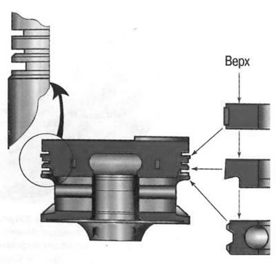
Fig. 5.3. Piston and piston rings.
Helpful tips:
- With a certain amount of skill and attentiveness, many engine and system faults can be determined quite accurately by the color of the smoke coming out of the exhaust pipe. Blue smoke indicates that oil is getting into the combustion chambers, and constant smoking is a sign of severe wear of the cylinder-piston group parts. The appearance of smoke during revving, after prolonged cranking by the starter, after long idling or immediately after engine braking usually indicates wear of the valve stem seals. Black smoke is a sign of too rich a mixture due to a faulty engine management system or injectors. Gray or thick white smoke with an admixture of moisture (especially after the engine overheats) means that the coolant has burst into the combustion chamber through a damaged cylinder head gasket. If this gasket is severely damaged, the liquid sometimes gets into the oil pan, the oil level rises sharply, and the oil itself turns into a cloudy whitish emulsion. White smoke (steam) with an unheated engine in damp or cold weather is normal.
- Quite often you can see a car standing in the middle of a city traffic jam with the hood open, emitting clouds of steam. Overheating. Of course, it is better not to allow this, looking at the temperature gauge more often. But no one is insured against the fact that the thermostat, electric fan may suddenly fail, or the coolant may simply leak. If you missed the moment of overheating, do not panic and do not aggravate the situation. Overheating is not as scary as its possible consequences. Never turn off the engine immediately - it will get a heat stroke and, perhaps, after cooling down, will refuse to start at all. After stopping, let it run at idle speed, while the circulation of liquid in the system will remain. Turn on the heater to maximum power and open the hood. If possible, pour cold water on the radiator. Only after achieving a decrease in temperature, stop the engine. But never immediately open the cap of the expansion tank: on an overheated engine, a geyser from under the open cap is guaranteed. Take your time, let everything cool down, and you will preserve the health of the car and your own health. Almost all car manuals recommend that you always depress the clutch when starting the engine. This recommendation is justified only in the case of starting in severe frost, so as not to waste battery energy on turning the shafts and gears of the gearbox in thickened oil. In other cases, this measure is aimed only at preventing the car from moving if a gear is engaged due to forgetfulness. Such a technique is harmful to the engine, since significant force is transmitted to the crankshaft thrust bearing through the squeezed clutch, and when starting (especially cold) lubrication does not reach it for a long time. The bearing wears out quickly, the crankshaft gets axial play, and starting from a standstill begins to be accompanied by strong vibration. In order not to damage the engine, get into the habit of checking the position of the gearshift lever before starting and starting the engine with the parking brake on, without squeezing the clutch unless absolutely necessary.
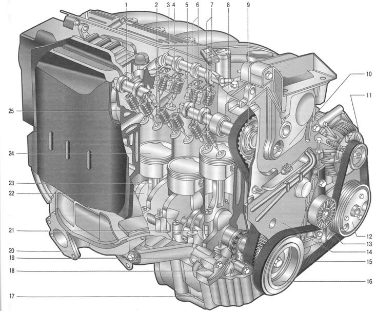
Fig. 5.4. K4M engine: 1 - exhaust camshaft; 2 - exhaust valve; 3 - intake camshaft; 4 - inlet valve; 5 - gi-valve pusher; b - valve rocker arms; 7 - valve springs; 8 - cylinder head cover; 9 - camshaft gear; 10 - front cylinder head cover; 11 - generator pulley; 12 - air conditioning compressor pulley; 13 - auxiliary drive belt tension roller; 14 - cylinder block; 15 - auxiliary drive belt; 16 - crankshaft pulley; 17 - oil pan; 18 - timing belt of the gas distribution mechanism; 19 - oil pump drive chain; 20 - exhaust manifold; 21 - connecting rod cover; 22 - crankshaft; 23 - connecting rod; 24 - piston; 25 - cylinder head
Possible engine malfunctions, their causes and solutions
| Cause of malfunction | Method of elimination |
| The engine won't start | |
| No fuel pressure in the rail: | |
| fuel lines are clogged | Flush and blow out the fuel tank and fuel lines |
| the fuel pump is faulty | Replace the pump |
| the fuel filter is clogged | Replace the filter |
| the fuel pressure regulator is faulty | Check the regulator, replace the faulty one |
| The ignition system pump is faulty | Cm. "Engine management system" |
| Engine runs rough or stalls at idle | |
| Insufficient pressure in the fuel rail | See the fault "Engine does not start" |
| The idle speed control valve is faulty | Replace the idle air control valve |
| The throttle position sensor is faulty or the throttle assembly is dirty | Replace the sensor or clean the throttle valve |
| Air leakage through the engine crankcase ventilation hoses and the hose connecting the intake pipe to the brake booster | Tighten the mounting clamps, replace damaged hoses |
| The ignition system is faulty | Cm. "Engine management system" |
| The variable valve timing system is faulty | Contact the service for diagnostics and repair of the system |
| The engine does not develop full power and is not responsive enough | |
| Incomplete throttle opening | Adjust the throttle actuator |
| Throttle position sensor is faulty | Replace the sensor |
| Insufficient pressure in the fuel rail | See the fault "Engine does not start" |
| The air filter is dirty | Replace the filter element |
| The ignition system is faulty | Cm. "Engine management system" |
| Clearances in the valve drive mechanism of K7J and K7M engines are damaged | Adjust the valve clearances |
| Wear of hydraulic valve compensators of the K4M engine | Replace hydraulic lifters |
| Insufficient compression - below 1 MPa (10 kgf/cm²): | |
| the cylinder head gasket is blown | Replace the gasket |
| burnt pistons, broken or stuck piston rings | Clean the rings and piston grooves from carbon deposits, replace damaged rings and pistons |
| poor valve seating | Replace damaged valves, polish seats |
| excessive wear of cylinders and piston rings | Replace pistons, bore and hone cylinders |
| The variable valve timing system is faulty | Contact the service for diagnostics and repair of the system |
| Insufficient oil pressure in a warm engine | |
| Using the wrong grade of oil | Replace the oil with the recommended one |
| Dilution or foaming of oil due to penetration of fuel or coolant into the oil pan | Eliminate causes of fuel or coolant leakage, change oil |
| Contamination of the working cavity or wear of the oil pump parts | Flush or replace the oil pump |
| Clogged oil filter | Replace the oil filter |
| Excessive reduction in clearance between the oil receiver and the bottom of the oil pan or damage to the oil receiver caused by impact with a road obstacle | Straighten the deformed oil pan, replace the damaged oil receiver if necessary |
| Increased clearance between main and connecting rod bearing shells and crankshaft journals | Grind the journals and replace the bearings |
| Cracks, pores in the walls of the cylinder block oil channels or clogged oil lines | Repair the cylinder block. If the defect cannot be eliminated, replace the block. |
| Cause of malfunction | Method of elimination |
| Knocking of crankshaft main bearings | |
| Usually a dull, metallic knock. It is detected when the throttle valve is opened sharply at idle. Its frequency increases with increasing crankshaft speed. Excessive axial clearance of the crankshaft causes a sharper knock, with uneven intervals, especially noticeable with a smooth increase or decrease in crankshaft speed. | |
| Insufficient oil pressure | See fault "Insufficient oil pressure in warm engine" |
| The flywheel mounting bolts are loose | Tighten the bolts to the recommended torque |
| Increased clearance between journals and main bearing shells | Grind the journals and replace the bearings |
| Increased clearance in the crankshaft thrust bearing | Replace the center main bearing shells, check the clearance |
| Knocking of connecting rod bearings | |
| Usually the knock of connecting rod bearings is sharper than the knock of main bearings. It can be heard at idle speed when the throttle valve is opened sharply. The place of knocking can be easily determined by disconnecting the spark plugs one by one (ignition coils on the K4M engine). | |
| Insufficient oil pressure | See the fault "Insufficient oil pressure in a warm engine". |
| Excessive clearance between the crankshaft journals and the bearings | Replace the bearings and grind the journals |
| Knocking of pistons | |
| The knock is usually soft, muffled, and is caused by the piston "beating" in the cylinder. It is best heard at low crankshaft speeds and under load. | |
| Increased clearance between pistons and cylinders | Replace pistons, bore and hone cylinders |
| Excessive clearance between piston rings and piston grooves | Replace rings or pistons with rings |
| Increased noise from the valve timing mechanism | |
| Low oil pressure in the lubrication system | See fault "Insufficient oil pressure on warm engine" |
| Increased clearances in the valve drive mechanism of K7J and K7M engines | Adjust the valve clearances |
| Wear of hydraulic valve compensators of the K4M engine | Replace hydraulic lifters |
| Valve spring failure | Replace the spring |
| Excessive clearance between the valve stem and the guide bushing caused by wear | Replace the valve and guide bushing |
| Camshaft cam wear | Replace the camshaft |
| A knock on a cold engine, audible for two to three minutes after starting and increasing in intensity as the crankshaft speed increases | |
| Increased clearance between pistons and cylinders | Piston knocking that disappears after the engine warms up is not a sign of a malfunction. If the knocking is constant, replace the pistons, bore and hone the cylinders |
| Loose crankshaft pulley fastening | Tighten the fastening |
| Brief knocking sounds immediately after starting the engine | |
| Using the wrong grade of oil (with reduced viscosity) | Replace the oil with the one recommended by the vehicle manufacturer |
| Increased crankshaft axial clearance | Replace the thrust half rings of the middle main bearing |
| Increased clearance in the front main bearing | Replace the main bearing shells |
| Knocking noises on a warm engine in idle mode | |
| Loose or worn accessory drive belt | Adjust the belt tension or replace it |
| Noise from the valve timing mechanism parts | See fault "Increased noise of the valve timing mechanism" |
| Using the wrong grade of oil | Replace the oil with the one recommended by the vehicle manufacturer |
| Increased clearances between piston pins and piston boss holes | Replace pistons and pins |
| Increased clearances between the crankshaft journals and the bearings | Replace the bearings and grind the journals |
| The axes of the upper and lower connecting rod heads are not parallel | Replace the connecting rod |
| Cause of malfunction | Method of elimination |
| Loud knocking in a warm engine when the crankshaft speed increases | |
| Crankshaft pulley hub failure | Replace damaged parts |
| Excessive tension of the accessory drive belt or the appearance of cracks and breaks on it | Adjust the belt tension, replace the damaged belt |
| The flywheel mount is loose | Tighten the flywheel mounting bolts to the specified torque |
| Excessive increase in clearances between the connecting rod and main bearing shells of the crankshaft | Regrind the journals to the repair size and replace the liners |
| Increased engine vibration | |
| Crankshaft imbalance | Remove and balance the crankshaft |
| Pistons of different weights are installed | Disassemble the connecting rod and piston group, select pistons by weight |
| Unequal clearances in the valve drive mechanism of K7J and K7M engines | Adjust the valve clearances |
| Wear of hydraulic valve compensators of the K4M engine | Replace hydraulic lifters |
| Uneven compression values in cylinders | cm. "Checking the compression in the cylinders" |
| The powertrain suspension mounts are badly worn or hardened | Replace the supports |
| Engine detonation knocks | |
| Using low octane gasoline | Fill with gasoline of the appropriate octane rating |
| The electronic engine control unit is faulty | Replace the block |
| The knock sensor is faulty | Replace the sensor |
| Increased oil consumption | |
| Oil leaking through engine seals | Tighten the fasteners or replace the gaskets and seals |
| The crankcase ventilation system is clogged | Flush the crankcase ventilation system components |
| Wear of piston rings or engine cylinders | Rebore cylinders, replace pistons and rings |
| Cause of malfunction | Method of elimination |
| Broken piston rings | Replace the rings |
| Coking of oil scraper rings or grooves in piston grooves due to the use of non-recommended oil | Clean the rings and grooves from carbon deposits, replace the engine oil with the recommended one |
| Worn or damaged valve stem seals | Replace the valve stem seals |
| Increased wear of valve stems or guide bushings | Replace valves, repair cylinder head |
| Engine overheating | |
| Insufficient amount of fluid in the cooling system | Add coolant to the cooling system |
| The outer surface of the radiator is heavily contaminated | Clean the outer surface of the radiator with a jet of water |
| Thermostat is faulty | Replace Thermostat |
| The electric fan of the cooling system is faulty | Check the fan motor and its relay, replace faulty components |
| The expansion tank cap valve is faulty (is constantly open, which is why the system is under atmospheric pressure) | Replace the expansion tank cap |
| Using low octane gasoline | Fill with gasoline of the appropriate octane rating |
| Rapid drop in fluid level in expansion tank | Rapid drop in fluid level in expansion tank |
| The radiator is damaged | Repair or replace the radiator |
| Damage to hoses or gaskets in pipeline connections, loose clamps | Replace damaged hoses or gaskets, tighten hose clamps |
| Fluid leaking through water pump seal | Replace the water pump |
| The cylinder head gasket is damaged | Replace the gasket |
| Fluid leakage through microcracks in the block or cylinder head | Check the tightness of the block and cylinder head; if cracks are found, replace damaged parts |