
Removing
Remove the seat and headrest.
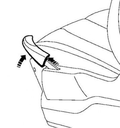
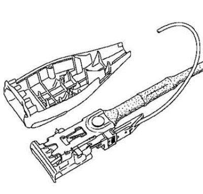
Pic. 8.112. Seat adjustment knob
Note. Protect the seat height adjustment knob (with protective tape), apply a light blow with a wooden mallet (on the back of the handle), while keeping the handle slightly raised (pic. 8.112).
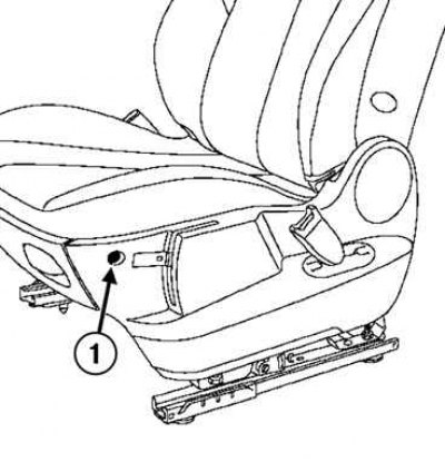
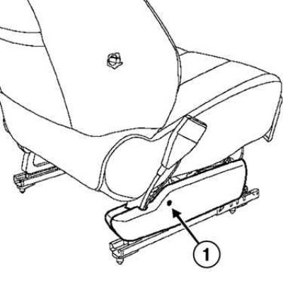
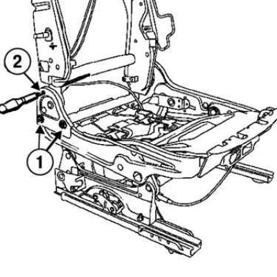
Pic. 8.113. Unscrewing the front screw securing the casing: 1 - front mounting screw
Loosen the front cover screw (pic. 8.113).
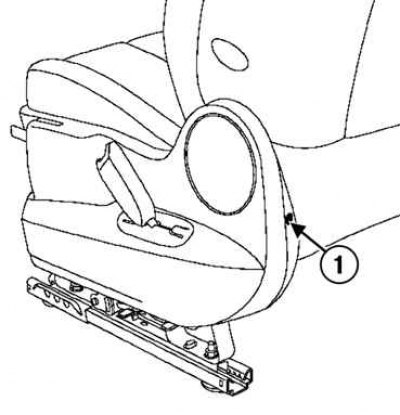
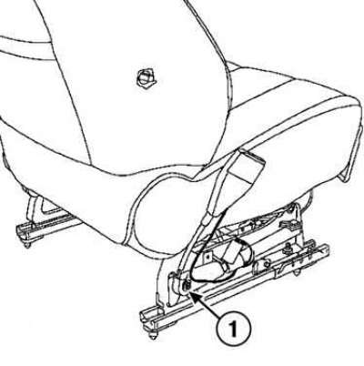
Pic. 8.114. Unscrewing the rear screw securing the casing: 1 - rear mounting screw
Loosen the rear cover screw (pic. 8.114).
Remove the cover.
Removing the seat height adjustment mechanism
Set the seat cushion to the up position (spring is completely loose).
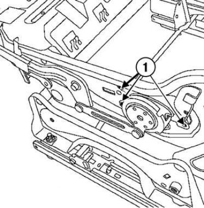
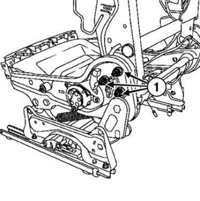
Pic. 8.115. Removing the rivets of the seat height adjustment mechanism: 1 - rivets
Remove the seat height adjuster rivets (pic. 8.115).
Remove the mechanism and handle.
Disconnect the seat belt pretensioner connector.
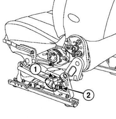
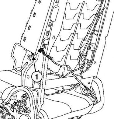
Pic. 8.116. Removing the seat belt pretensioner mount: 1 - connector; 2 - bolt
Loosen the seat belt pretensioner bolt (pic. 8.116).
Pic. 8.117. Removing the headrest guide covers: 1 - covers
Remove the headrest guide covers (pic. 8.117).
Pic. 8.118. Removing the seat back lumbar support adjustment knob cover
With a special tool (Sag. 1597) remove the seat back lumbar support adjuster cover (pic. 8.118).
Pic. 8.119. Removing the seat back lumbar adjustment handle
Remove the backrest lumbar support adjustment knob using a flat blade screwdriver (pic. 8.119).
Pic. 8.120. Removing the cover: 1 - fastening screw
Loosen the cover screw and remove the cover (pic. 8.120).
Disconnect the pretensioner connector.
Pic. 8.121. Removing the seat belt buckle bolt: 1 - bolt
Loosen the seat belt buckle (pic. 8.121).
Pic. 8.122. Seat belt buckle
Note. To disconnect the connector, unscrew the screws securing both lock covers (pic. 8.122).
Remove the seatback upholstery.
Pic. 8.123. Removing the headrest guides
Remove the headrest rails (pic. 8.123).
Disconnect the wiring harness and wire from the airbag outlet.
Pic. 8.124. Rivet drilling: 1 - rivet
Drill out the rivet (pic. 8.124).
Remove the airbag.
Disconnect the wire from the outlet.
Pic. 8.125. Disconnecting the airbag switch: 1 - switch
Disconnect switch (pic. 8.125).
Remove the seat cushion upholstery.
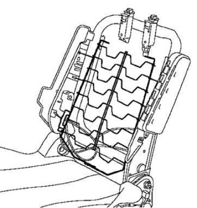
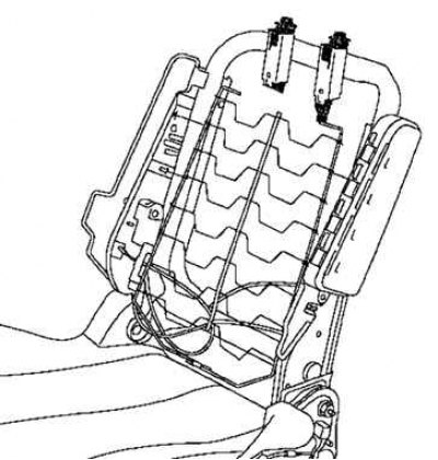
Pic. 8.126. Removing the grid mechanism for adjusting the lumbar support of the seat back
Remove the seat back lumbar adjustment mesh (pic. 8.126).
Remove the drive cable sheath retainers.
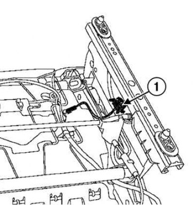
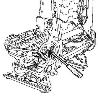
Pic. 8.127. Seat lumbar adjustment rivet: 1 - rivet
Drill out the rivet of the seat lumbar adjustment mechanism (pic. 8.127).
Remove the mechanism.
Pic. 8.128. Unscrewing the screw securing the seat adjustment handle in the longitudinal direction
Loosen the screw securing the seat adjustment knob in the longitudinal direction (pic. 8.128).
Remove the handle (The operation is the same as removing the seat back adjustment knob).
Pic. 8.129. Removing the locking cable
Remove the locking mechanism cables (pic. 8.129).
Remove the front cover.
Pic. 8.130. Removing the seat back lock
Disconnect the seat back lock link (pic. 8.130).
Remove the rope.
Pic. 8.131. Removing the cable sheath stoppers: 1 - stoppers
Detach the mesh and cable sheath stoppers (pic. 8.131).
Removing the backrest and seat cushion
Insert a metal rod through the opening of the frame on both sides, if necessary, secure it with a belt.
Before proceeding, make sure that the rod is installed securely.
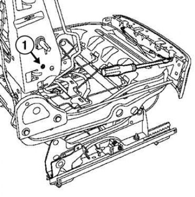
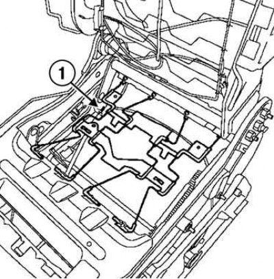
Pic. 8.132. Frame bolts: 1 - bolts; 2 - metal rod
Turn away bolts (pic. 8.132).
Attention! Leave the rod in place while removing the seat.
Pic. 8.133. Removing the seat back frame: 1 - fastening bolts
Unscrew the mounting bolts and remove the seat back frame (pic. 8.133).
Installation
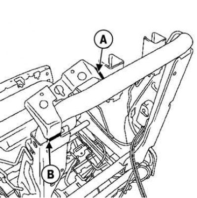
Pic. 8.134. Backrest Lock Bracket Cutting Marks
Cut the backrest lock bracket at marks A and B (pic. 8.134).
Attention! Before starting the operation, make sure that the ring is securely attached, if in doubt, thread the rod on both sides of the frame.
Preliminary and final tightening of frame fastening parts:
- pre-tightening torque of nuts 20 Nm;
- back nuts 66 Nm;
- backrest bolts 25 Nm.
Features of installing an anti-slip cushion
Tighten the anti-slip cushion mounting bolts to the required torque of 80 Nm.
Bolt tightening order:
- left front bolt;
- right front bolt;
- rear center bolt;
- rear right and left bolts.
Install the remaining components in the reverse order of removal.
Attention! Before installing the seatback upholstery, check that the fasteners are well glued «Velcro» on the foam seat back padding.