



Contents: Assembling the supercharger 🠛 Supercharger motor resistor 🠛 Air distribution block 🠛 Heater matrix 🠛
Assembling the supercharger
Removal
1. Disconnect the negative cable from the battery.
2. Remove the wiper arms (see Section 12) and windshield fairing (Section 11).
3. Remove the jack from the engine compartment.
4. On fuel injected models, remove the electronic module from the right side of the air intake box (see section 4B or 4C).
5. Remove the heater blower cover - it is secured with two screws (see illustration).
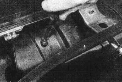
12.5. Remove the heater blower cover screw.
6. Disconnect the supercharger resistor multi-pin connector (see illustration).
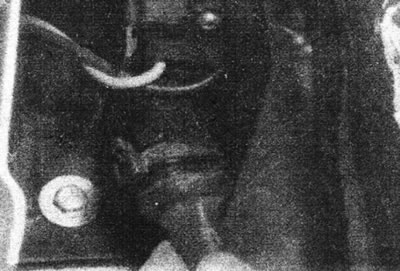
12.6 Disconnect the multi-pin connector from the supercharger resistor.
7. Remove the two supercharger mounting bolts. Remove the supercharger from its operating position and remove it through the air intake box (see illustrations).
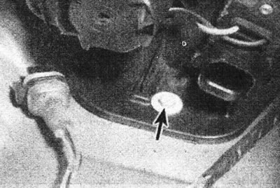
12.7a. One of the supercharger mounting bolts (marked with an arrow).
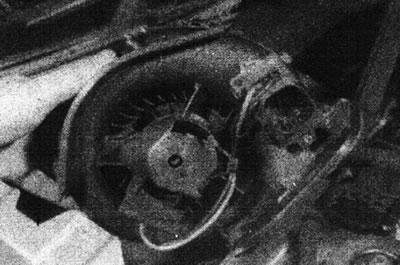
12.7b. Remove the supercharger.
8. If the motor is to be replaced, release the clips and separate the housing halves. Use new staples when assembling (supplied with a new motor).
9. Inspect the seal at the base of the supercharger and replace it if the condition of the component is in question.
Note: If the seal is defective, rainwater entering the air intake box will leak into the vehicle interior.
Installation
10. Install in reverse order.
Supercharger motor resistor
Removal
11. The resistor is located on the right wall of the supercharger housing. It switches the engine to low and medium speed. If a component fails, the motor will not operate at one or more speeds.
12. Access the supercharger assembly as described above and disconnect the resistor multi-pin connector. Also disconnect the blower motor multi-pin connector (see illustration).
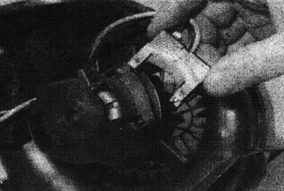
12.12. Disconnect the blower motor multi-pin connector.
13. Remove the two screws, release the clips and take out the resistor (see illustrations).
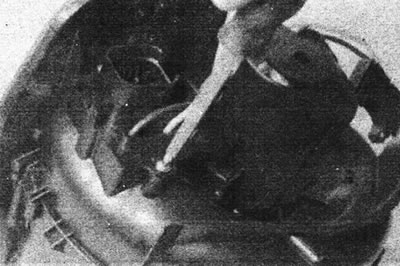
12.13a. Remove the screws...
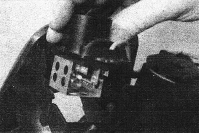
12.13b... release the clips and remove the resistor.
Installation
14. Install in reverse order.
Air distribution block
Removal
15. Remove the instrument panel assembly.
16. Remove the supercharger assembly as described above.
17. Remove the mounting screw, now accessible from the air intake box (see illustration).
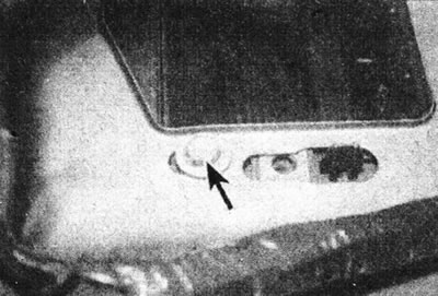
12.17. Air distributor unit mounting screw (marked with an arrow) accessible only after removing the supercharger.
18. Clamp the cooling system hoses near the bulkhead. Alternatively, drain the cooling system (see Section 1). Disconnect the hoses from the heater matrix pipes (see illustration).
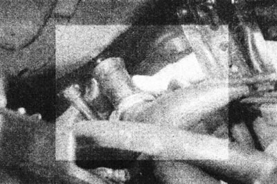
12.18. Disconnect the heater hoses; they are different sizes so they cannot be mixed up.
19. Remove the two screws and separate the air duct panel from the air distributor assembly, bending the center instrument panel bracket back if necessary (see illustration).
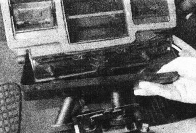
12.19. Remove the air duct panel from the air distributor unit.
20. Remove the air distributor unit together with the control panel and cables (see illustration).
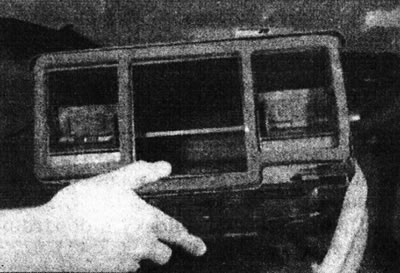
12.20. Remove the air distributor unit, control panel and cables.
Be prepared for coolant to exit the heater matrix.
Installation
21. Install in reverse order. Bring the coolant level in the cooling system to normal and bleed it (Section 1).
Heater matrix
Removal
22. Remove the air distributor unit as described above.
23. Remove the foam seal and cover plate from the heater matrix pipes (see illustration).
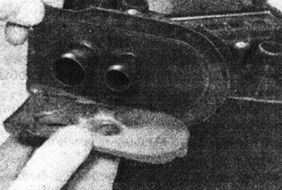
12.23. Remove the seal and closing plate from the heater matrix pipes.
24. Remove two screws (if any), release the clamps and remove the heater matrix (see illustrations).
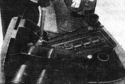
12.24a. Remove the heater matrix mounting screws, if any...
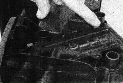
12.24b.... release the staples...
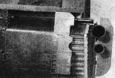
12.24s.... and remove the heater matrix.
Do not damage its plates.
Installation
25. Install in reverse order. If the brackets have been damaged, attach the matrix with two screws, screwing them into the existing holes.