
The corrector control unit is located on the left side of the instrument panel.
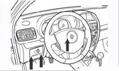
Figure 8.58. Removing the headlight range control unit (the arrows show where the screwdriver is to be inserted)
To remove the control box, use a small flat-blade screwdriver to depress the holder's spring clips by inserting the screwdriver into the locations shown in Figure 8.58. Be careful not to damage the plastic.
Disconnect the connector, and then disconnect the control unit from the holder.
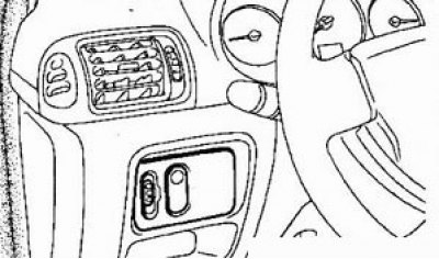
Regulator switch
Remove the switch from the panel with a small screwdriver, disconnect the switch connector.
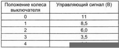
Examination
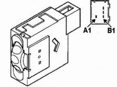
Terminal A1 - Power, Terminal B1 - "Earth", Terminal B2 - Low beam signal, Terminal B3 - Control signal.
To remove the actuator, it is necessary to remove the headlamp.
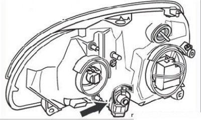
Figure 8.59. Removing the headlight range control actuator from the headlight (arrow)
Rotate the actuator 1/8 turn to disengage it from the headlight assembly (Figure 8.59).
Slightly rocking the actuator, disconnect the ball joint from the parabolic reflector.
To facilitate installation of the actuator, remove the sealed cover and hold the headlamp reflector. Then insert the ball joint into its seat.
Install the actuator into the headlight assembly and turn it 1/8 turn.
Reinstall the headlight and proceed to adjust the headlights.