



Necessary tool
- Fre. 823 Device for returning the piston of the brake cylinder.
- Emb. 880 Inertial puller.
- Rou. 943 Hub cap remover.
Tightening torques, Nm
- Wheel mounting bolts 90.
- Hub nut 175.
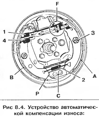
A - Primary shoe;
B - Secondary shoe;
C - Fixed support plate;
R - Support heel of the shoe;
F - Automatic wear compensation device;
1 - Upper tension spring;
2 - Lower tension spring (to press the support heels of the pads against the support plate);
3 - Side shoe retainer;
4 - Return spring of the release lever.
Removal
Attention! Brake pads must be replaced completely; it is not allowed to install pads from different manufacturers or of different quality at the same time.
1. Remove the brake drum.
2. Remove the lower tension spring 2 using tension spring pliers.
3. Using adjustable pliers, remove the springs of the side brake shoe retainers.
4. Alternately remove the heels of the pads from the fixed support plate.
5. Bring the heels of the pads together to move the toes of the pads away from the ends of the working cylinder.
6. Disconnect the unit (automatic wear compensation device and pads) from the brake shield, then remove it after releasing the brake cable from the holder.
Installation
1. Install the assembled unit on the vehicle.
2. Install the brake cable onto the release lever.
3. Bring the heels of the pads together and place the toes on the pistons of the working cylinder.
Caution: Do not damage the dust covers.
4. Place the heels of the pads on the fixed support plate C.
5. Install the side clamps 3.
6. Remove the clamps from the pistons of the working cylinders.
7. Install the lower tension spring 2.
Adjustment
1. Using a screwdriver, adjust the brake pad circle diameter using the ratchet wheel of the automatic wear compensation device.
2. Install the drums without tightening the mounting nuts.
3. Center the position of the brake pads by repeatedly pressing the brake pedal (about 20 times).
4. Check the correct operation of the automatic wear compensation device (by a characteristic click inside the drum).
5. Remove the drums.
6. Ensure that the brake cables slide freely.
7. Ensure that the brake shoe release levers L contact correctly.
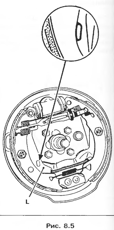
8. Gradually tighten the cables on the adjuster assembly so that the release levers L begin to move between the first and second clicks of the parking brake actuator lever stroke and remain pressed from the second click.
9. Secure the adjusting unit lock nut.
10. Install the brake drums and tighten the mounting nuts to a torque of 175 Nm.
11. Install the hub caps.
[This note was copied from the resource: RENAULTBOOK.ru]