



Contents: Inspection 🠛 Right upper engine mount bracket 🠛 Right Lower Engine Mount…🠛 Right engine mount rubber 🠛 Right engine limiter 🠛 Left Upper…🠛 Left engine/gearbox mount bracket…🠛 Rear engine mount bracket/lower link 🠛
Inspection
1. Apply the handbrake, then jack up the front of the car and support it securely on axle stands.
2. Visually inspect the rubber mounts on the engine/transmission mounts for cracks and dirt. Carefully use a lever to determine the condition of the rubber cushions. If there is excessive movement in the mount, or if the rubber condition has deteriorated, the mount should be replaced.
Right upper engine mount bracket
Removal
3. Place the jack under the pallet with a large block of wood between them. Raise the engine slightly.
4. Loosen the nut securing the bracket to the engine mount rubber and remove the rubber pad, then loosen the three bolts securing the bracket to the lower engine mount bracket/timing belt cover and remove the bracket (see illustrations).
Information is located on the website: Renaultbook.ru
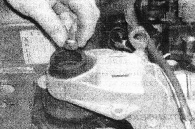
17.4a. Unscrew the nut securing the right upper bracket to the rubber mount...
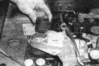
17.4b....and remove the rubber cushion...
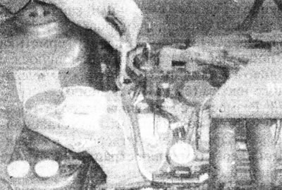
17.4 sec....then unscrew the bolts securing the bracket to the lower mount bracket...
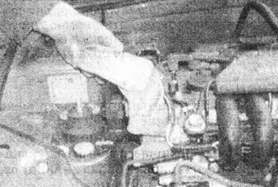
17.4d....and remove the top bracket.
Installation
5. Install in reverse order, tighten the fastening nut and bolts to the tightening torque specified in the Specifications. Finally, check and, if necessary, adjust the position of the engine travel limiter as follows.
6. Measure the gap between each side of the travel limiter rubber and the hanger bracket. This can be done by inserting a metal plate or feeler gauge of suitable thickness through the two slots in the top of the bracket. The gap on both sides must be the same, i.e., the rubber of the travel limiter must be located strictly in the center of the bracket.
7. If necessary, loosen the two bolts securing the travel limiter plate to the body and adjust the position of the limiter. Finally, tighten the mounting bolts securely.
Right Lower Engine Mount Bracket/Timing Belt Cover
Removal
8. Remove the right upper hanger bracket as described earlier in this Chapter.
9. Release the charcoal canister hose from the front of the lower engine mount bracket/timing belt cover (see illustration).
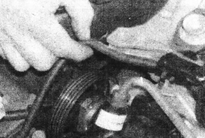
17.9. Release the carbon canister hose from the front of the bracket.
10. Disconnect the wiring from the following components, then move the harness away from the lower engine mount bracket/timing belt cover, noting the location of the wires (see illustrations).
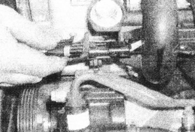
17.10a. Disconnect the fuel injector harness wiring...
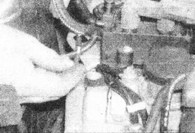
17.10b...and the wiring of the car radio interference suppressor.
- Oxygen sensor.
- Ignition control module.
- Fuel injector wiring harness.
- Car radio interference suppressor.
11. Unscrew the car radio interference suppressor from the valve cover (see illustration).
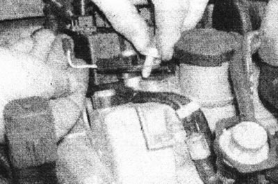
17.11. Unscrew the interference suppressor from the valve cover.
12. Release the coolant hose from the clip on the plastic cover of the toothed drive belt (see illustration).
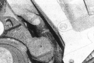
17.12. Release the cooling system hose from the clamp on the timing belt cover.
13. Carefully remove the clamp securing the fuel hoses to the rear of the lower engine mount bracket/timing belt cover, then release the hoses from the upper bracket/cover (see illustrations).
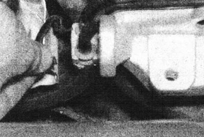
17.13a. Remove the bracket securing the fuel hoses to the rear of the bracket/cover.
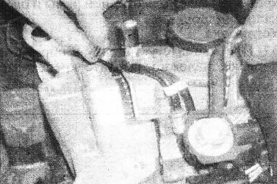
17.13b....then release the hoses from the top of the bracket/cover.
14. Remove the four bolts securing the lower engine mount bracket/timing belt cover to the cylinder head, then slide the bracket/cover past the coolant hose and remove the assembly from the engine compartment (see illustrations).
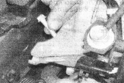
17.14a. Loosen the mounting bolts...
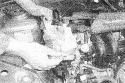
17.14b....then remove the timing belt bracket/cover.
Installation
15. Perform installation in reverse order, securely tighten the mounting bolts and install the right upper engine mount bracket as described earlier in this chapter. Ensure the wiring is routed correctly, as noted before removal.
Right engine mount rubber
Removal
16. The rubber cushion is mounted in a metal mounting plate, which is bolted to the body.
17. Remove the right upper engine mount bracket as described earlier in this Chapter.
18. Remove the four mounting bolts, two of which also secure the engine limiter, then remove the limiter and remove the rubber mount/bracket assembly.
Installation
19. Install in reverse order, but do not tighten the two hanger/stopper mounting bolts until the upper engine mount bracket has been installed as described earlier in this Chapter.
Right engine limiter
Removal
20. Remove the right upper engine mount bracket as described earlier in this Chapter.
21. Unscrew the two mounting bolts that also secure the engine mount and remove the limiter.
Installation
22. Install in reverse order, do not fully tighten the travel limiter mounting bolts until the upper engine mount bracket has been installed as described earlier in this Chapter.
Left Upper Engine/Transmission/Battery Bracket
Removal
23. Attach a winch and lifting device to the left engine mounting eye and lift the engine slightly.
24. Remove the battery as described in Section 5A.
25. Remove the fuel injection system processor unit as described in Section 4C.
26. Release the wiring, cables, hoses, etc. from the bracket.
27. Unscrew the battery side plate from the bracket and remove it (see illustrations).
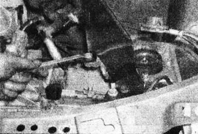
17.27a. Unscrew the mounting bolts...
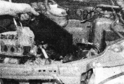
17.27b....and remove the battery side plate.
28. Carefully mark the position of the bracket on the body.
29. Remove the two nuts securing the suspension bracket to the gearbox bracket, then remove the four bolts securing the bracket to the body and remove it from the engine compartment (see illustrations).
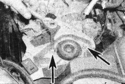
17.29a. Remove the two nuts securing the suspension/battery bracket to the gearbox bracket...
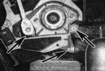
17.29b....three upper bolts (marked with arrows), fastening the bracket to the body...
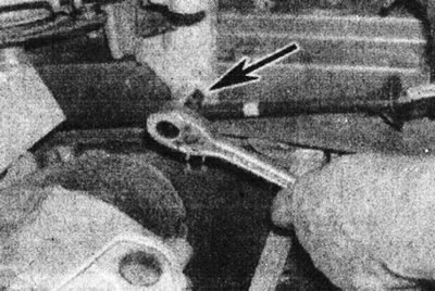
17.29s....and the lower bolt securing the bracket to the body,...
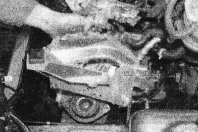
17.29d....then remove the bracket.
Installation
30. Install in reverse order, tighten the mounting bolts to the tightening torque specified in the Specifications.
Left engine/gearbox mount bracket rubber
Removal
31. Remove the left upper engine/transmission/battery bracket as described earlier in this Chapter.
32. Unscrew the fastening nut and remove the rubber cushion from the stud on the gearbox.
Installation
33. Install in reverse order, tighten all fasteners to the tightening torque specified in the Specifications.
Rear engine mount bracket/lower link
Removal
34. Apply the handbrake, then jack up the front of the car and place it on axle stands.
35. Working under the car, unscrew the bolts (lock the nuts with a second wrench), securing the rear suspension support fork to the brackets on the subframe and cylinder block, note the location of the washers and spacers on the bolts. Remove the unit from under the vehicle.
36. If necessary, unscrew and remove the brackets from the engine subframe and cylinder block.
Installation
37. Reinstall in reverse order, tightening the fastening nuts and bolts securely.