



Contents: General description 🠛 Precautions 🠛
General description
The fuel system consists of a fuel tank, a fuel filter with a water separator, a high-pressure fuel pump, injectors and related components. When passing through the filter, the fuel is heated by a special element installed in the filter housing. The exhaust system is a conventional type, but some models may be equipped with an exhaust gas recirculation system and/or a non-controlled catalytic converter, which reduce the amount of harmful impurities in the exhaust gas (see Section 4E).
Fuel is pumped from the fuel tank by a high-pressure fuel pump. Before reaching the pump, the fuel passes through a fuel filter, where it is cleaned of foreign objects and water. Excess fuel lubricates the rotating components of the pump and then returns to the tank (see illustrations).
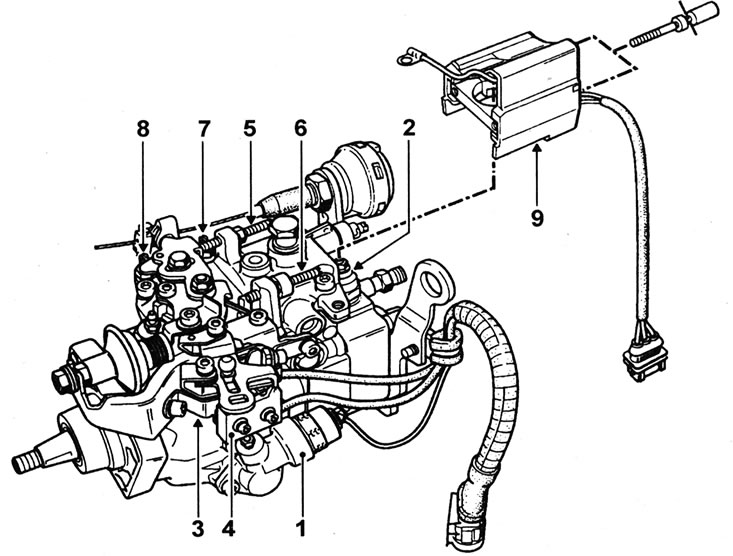
1.2a. Bosch high-pressure fuel pump components: 1 - Load-sensing solenoid valve (ALFB); 2 - Fuel cut-off valve coil; 3 - Post-heating/exhaust gas recirculation valve microswitch; 4 - Air conditioner microswitch; 5 - Deceleration frequency adjustment screw; 6 - Maximum speed adjustment screw; 7 - Idle speed adjustment screw; 8 - Fast idle speed adjustment screw; 9 - Electronic unit of the coded valve.
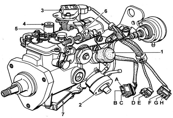
1.2b. Lucas High Pressure Fuel Pump Components: 1 - Injection advance corrector; 2 - Boost pressure corrector; 3 - Throttle lever potentiometer; 4 - Injection timing control hole plug; 5 - Idle speed adjustment screw; 6 - Deceleration frequency adjustment screw; 7 - Electronic unit of the coded valve; A - Earth; B - "+" after ignition; C - Coded Line; D - Injection advance corrector control; E - "+" after ignition; F - Earth; G - Throttle control lever signal; H - 5V power supply to the throttle lever potentiometer.
The high-pressure fuel pump is driven by a toothed belt and rotates at a speed that is half the crankshaft speed.
The F8Q 620 engine is equipped with a Bosch fuel pump. The high pressure required to inject fuel into the compressed air in the combustion chamber is achieved by a cam plate acting on a separate piston. Fuel passes through a central rotor with one outlet port, which is alternately aligned with the outlet channels of the injectors.
Fuel dosage is controlled by a centrifugal regulator, which responds to the position of the gas pedal and the engine speed. The regulator is connected to a metering valve, which increases or decreases the amount of fuel injected with each pump stroke.
The main injection point is set by the manufacturers during pump installation. When the engine is running, the injection timing is automatically adjusted to the crankshaft speed by means of a special mechanism that rotates the cam plate or ring.
The solenoid valve on the pump is used for short-term correction of the injection timing during cold starting.
The solenoid valve is controlled by the pre/post heating system control unit or the altitude sensor. When the coolant temperature is less than 29°C, power voltage is supplied to the valve coil when the engine is started. If the coolant temperature sensor is defective, the further operation of the valve will depend on the air temperature, which is measured by the temperature sensor installed on the control unit. If both sensors are faulty, the solenoid valve is automatically turned on for 200 seconds each time the engine is started. It is also supplied with current through a relay, which is controlled by an altitude sensor when the ambient pressure reaches 900±20 mBar.
The F8Q 784, 786 and 788 engines are equipped with a Lucas DPC fuel pump.
This pump consists of an injection advance corrector controlled by an electronic unit. Fuel in the pump passes into the hydraulic head through a metering valve connected to the gas pedal cable and the boost pressure corrector. The hydraulic head consists of two pistons directed in opposite directions, held together by rollers moving in a ring. The injection moment is determined by the signal coming from the needle lift sensor of the 1st injector.
A separate device is also designed to increase fuel supply as boost pressure increases.
Four fuel injectors inject fuel into swirl chambers mounted in the cylinder head. The injectors are calibrated to open and close only at specific pressures, ensuring efficient ignition of the fuel-air mixture. The injector needle is lubricated with fuel, which accumulates in the spring chamber and is directed to the return hose of the fuel pump through the outlet pipe.
Cold starting is aided by a heater or glow plugs installed in each swirl chamber (see Section 5D).
The fast idle system is controlled by a thermal actuator or a vacuum actuator, depending on the model.
On models with thermally controlled fast idle speed control (f8Q 620 engines), a temperature sensor in the cooling system controls the fast idle lever on the fuel pump via a cable, increasing the idle speed until the engine is warmed up.
On vacuum-driven models (f8Q engines 784, 786 and 788), the fast idle speed cable is controlled by a vacuum drive via an electromagnetic unit. The solenoid is controlled by the glow plug control unit and on models with air conditioning there is additional control from the compressor clutch relay.
The shut-off valve stops the fuel supply to the fuel pump rotor when the ignition is off.
Provided the maintenance specified in the Specifications is carried out diligently, the fuel injection system will provide a long service life. The fuel pump can outlive the engine. The main potential cause of damage to the fuel pump and injectors is dirt or water in the fuel.
Servicing of the fuel pump and injectors is limited to the car owner and any work not described in this Section must be carried out by a Renault dealer or a fuel injection specialist.
Precautions
Warning: When working with fuel system components, especially fuel injectors, certain precautions must be taken. See warnings at beginning of Chapters.