



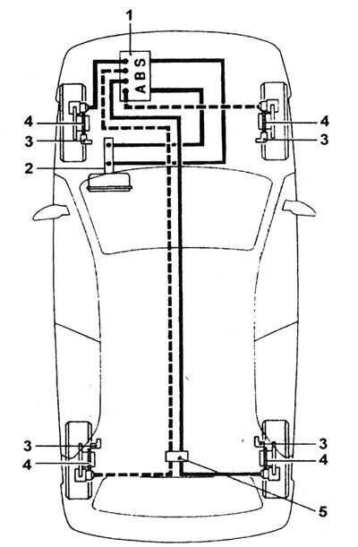
22.1. Location of ABS components: 1 - Assembling the modulator; 2 - Master cylinder and booster; 3 - Wheel speed sensor; 4 - Slip ring; 5 - Load-sensing brake pressure control valve.
2. The main components of the system are four wheel speed sensors (one per wheel) and a modulator unit, which contains the ABS electronic control unit, hydraulic valves and accumulators, and a return electric pump.
3. The electromagnetic valves are controlled by an electronic control unit, which receives signals from the wheel speed sensors. The sensors detect the rotation speed of a toothed contact ring attached to the wheel hub. By comparing the rotation speed signals of all four wheels, the electronic control unit determines which one is close to locking. In normal mode, the system operates in the same way as a non-ABS braking system (see illustration).
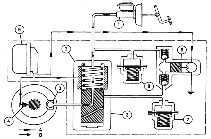
22.3. Normal operation of the ABS system: 1 - Master cylinder; 2 - Solenoid valve; 3 - Brake caliper; 4 - Wheel speed sensor and slip ring; 5 - ABS electronic control unit; 6 - Return pump; 7 - Accumulator; 8 - Accumulator; A - Supply of electrical signal; B - Brake fluid flow.
[View the original on the specified resource www.renaultbook.ru]
4. If the electronic control unit detects that the brakes are about to lock, it switches the ABS system to pressure maintenance mode (see illustration).
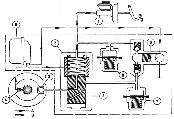
22.4. Stage of maintaining pressure in the ABS system The keys are shown in Illustration 22.3.
The electronic unit activates the corresponding electromagnetic valve of the modulator unit. The valve closes the supply of fluid to a given brake unit, stabilizing the hydraulic pressure at a given level.
5. If the rotation speed of this wheel continues to decrease disproportionately, the ABS system begins to operate in pressure reduction mode (see illustration).
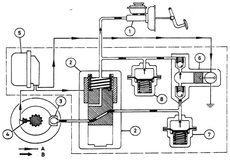
22.5. Stage of pressure reduction in the AVR system The keys are given in Illustration 22.3.
The return pump pumps brake fluid from this circuit back to the master cylinder, thereby reducing the pressure in the brake assembly close to locking. When the wheel speed returns to an acceptable value, the pump switches off and the solenoid valve opens, returning the hydraulic pressure to its previous value. This cycle can repeat up to 10 times per second.
6. The operation of the electromagnetic valve and the return pump creates pulses in the hydraulic line. When the ABS system is functioning, these pulses are felt on the brake pedal.
7. The valves associated with the front brake calipers operate independently, but the valve of the rear brake assemblies, together with the load-sensing control valve, control both assemblies simultaneously. Since the brake hydraulic line is divided diagonally, a separate mechanical valve in the modulator block divides the hydraulic line of the rear brake valve into two separate circuits.
8. The operation of the ABS system depends entirely on electrical signals. To prevent the system from reacting to extraneous signals, it has a built-in safety circuit that monitors all pulses received by the electronic control module. If such a signal is detected or the battery voltage is low, the ABS system is automatically disabled and a warning lamp on the instrument panel lights up. The braking system operates as a conventional system without ABS.
9. If there is a fault with the ABS system, contact your Renault dealer. However, first make sure the problem is not caused by poor wiring connections.