



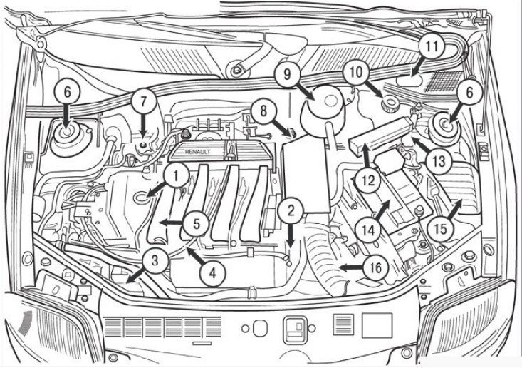
Figure 2.24. Location of units and service points in the engine compartment: 1 – engine oil filler cap; 2 – oil dipstick; 3 – Power steering pump; 4 – accelerator pedal cable; 5 – inlet manifold; 6 – upper supports of the front suspension struts; 7 – brake system reserve tank; 8 – air filter; 9 – expansion tank of the engine cooling system; 10 – reserve tank of the power steering system; 11 – Windshield washer fluid reservoir; 12 – Electronic control unit (ECU); 13 – inertial fuel shut-off valve; 14 – Battery; 15 – fuse box; 16 – air intake duct
Before starting work, you must familiarize yourself with the section of the book that describes the design, rules for removing and installing a specific unit or assembly.
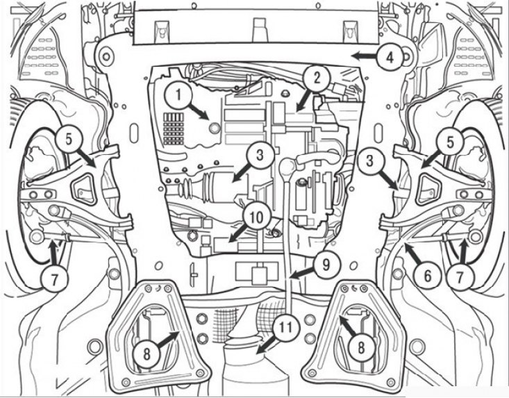
Figure 2.25. View of the front of the car from below: 1 – engine oil pan drain plug; 2 – gearbox (mechanical); 3 – front wheel drive shaft; 4 – front suspension subframe; 5 – lower arms of the front suspension; 6 – anti-roll bar; 7 – steering rod end; 8 – subframe reinforcement; 9 – gear shift mechanism rod; 10 – steering mechanism; 11 – catalytic converter of the exhaust system
The units located in the underhood space and their service points are shown in Figure 2.24. Figure 2.25 shows a view from below the front of the vehicle.
Original version on our portal: renaultbook
Any type of work must begin with a thorough car wash, preparation of the workplace, documentation, consumables and tools.
When performing operations on the body, all paintwork on working surfaces must be protected by soft covers, blankets or fender linings.
If you encounter technical problems with disassembling a particular unit, determine the full technology for performing them, consult with someone who has already performed this work, or contact the nearest Renault service station.