
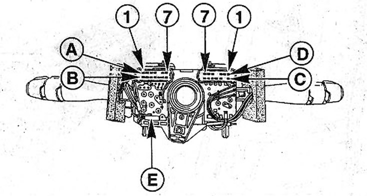
31.0 Assignment of the steering column switches
Glass cleaner switch
Plug strip A (see illustration 31.0):
- A1 - interval windshield wiper.
- A2 - accelerated mode of operation of the cleaner.
- AZ - slow mode of operation of the glass cleaner.
- A4 - not used.
- A5 - parking position.
- A7 - (+) to the windshield wiper motor.
Plug B:
- B1 - rear window washer pump
- B2 - interval operation mode of the rear window cleaner.
- VZ - not used.
- AT 4 - (+) to the rear window wiper motor.
- AT 5 - «weight» (-) on-board computer mode selection buttons.
- B6 - not used.
- B7 - on-board computer mode selection button / daily mileage reset button.
Attention! The resistance of the intermittent wiper rheostat can be measured at terminals A1 and A7.
Wiper Modes: Park Position = 10 kΩ
- 1st position = 8 kΩ
- 2nd position = 5 kΩ
- 3rd position = 2.5 kΩ
- 4th position = 0 ohm
Make sure that the two-prong plug E is correctly installed (see illustration 31.0).
Switch for lighting, turn signal and horn
Plug strip C:
- C1 - fog lights.
- C2 - not used.
- SZ - fog lamp.
- C4 - sound signal.
- C5 - right turn indicator.
- C6 - light alarm.
- C7 - left turn indicator.
Plug strip D:
- D1 - parking lights.
- D2 - constant power (parking lights).
- D3 - constant power (dipped beam).
- D4 - not used.
- D5 - low beam.
- D6 - constant power (high beam).
- D7 - high beam.