



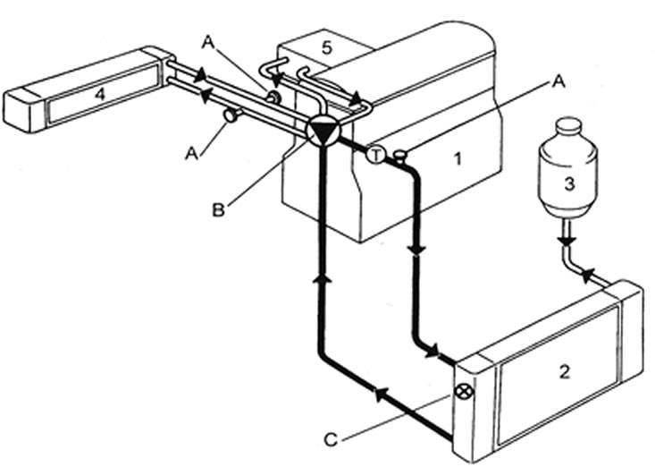
1.1a. Cooling system design - C series engine: 1 - Cylinder block; 2 - Radiator; 3 - Expansion tank; 4 - Heater matrix; 5 - Intake manifold; A - Bleed nipple; B - Water pump; C - Fan thermal switch; T - Thermostat.
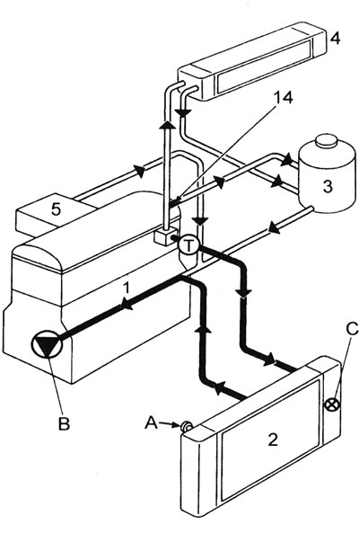
1.1b. Cooling system design - E series engines: 1 - Cylinder block; 2 - Radiator; 3 - Expansion tank; 4 - Heater matrix; 5 - Intake manifold; 14 - Limiter; A - Bleed nipple; B - Water pump; C - Fan thermal switch; T - Thermostat.
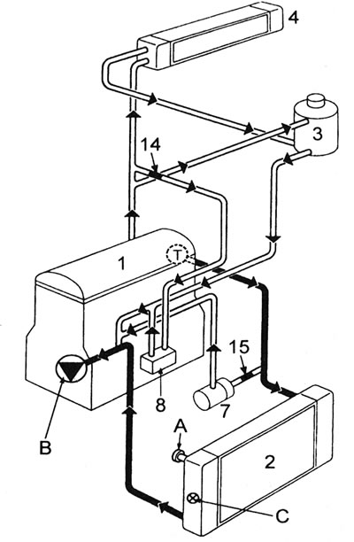
1.1c. Cooling system design - F7P engine (with 16 valves): 1 - Cylinder block; 2 - Radiator; 3 - Expansion tank; 4 - Heater matrix; 7 - Auxiliary water pump; 8 - Engine oil cooler; 14 - Limiter; 15 - Limiter; A - Bleed nipple; B - Water pump; C - Fan thermal switch; T - Thermostat.
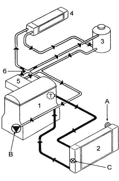
1.1d. Cooling system design - F3P engines: 1 - Cylinder block; 2 - Radiator; 3 - Expansion tank; 4 - Heater matrix; 5 - Intake manifold; 6 - Limiters; A - Bleed nipple; B - Water pump; C - Fan thermal switch; T - Thermostat.
2. The system functions as follows. Cold coolant is supplied from the base of the radiator through the lower hose to the pump, which forces it into the channels of the engine cooling jacket. After cooling the cylinders, combustion chambers and valve seats, the liquid reaches the thermostat, which is initially closed. The coolant passes through the heater and intake manifold and returns to the water pump.
3. When the coolant heats up to a certain temperature, the thermostat opens and the coolant flows through the upper hose into the radiator. Passing through the radiator, it is cooled by the air flow generated by the vehicle's movement, as well as by the electric fan (when necessary). The cold fluid returns to the engine and the cycle repeats.
4. As the engine heats up, the coolant expands and some of it is forced into the expansion tank. The C-series engines use a "cold" expansion tank - the displaced fluid is collected in it and returned to the radiator when the system cools down. All other models are equipped with a "hot" reservoir through which coolant circulates all the time the engine is running.
5. The electric fan, installed behind the radiator, is controlled by a thermal switch screwed into the radiator. When the coolant reaches a certain temperature, the switch contacts close, activating the fan (via relay).
6. Cooling system on models with F7P engine (with 16 valves) has two additional components: engine oil cooler (installed under the oil filter) and an auxiliary water pump (described below in this Section).
7. Air conditioning systems and the precautions to be taken when working with them are described in Chapter 15.