



Note: The inner joints of the front wheel drives are different in design, so the left and right drives are partially removed using different techniques, described separately for each drive.
You will need: all tools to remove the engine crankcase protection (see "Removal and installation mudguards and engine crankcase protection"), disconnecting the ball joint from the steering knuckle (see "Replacing the front suspension arm"), steering rod from the steering arm (see "Replacing the outer tie rod end"), to unscrew the nut of the upper shock absorber strut mount (see "Removal and installation the shock absorber strut"), as well as socket heads "13", "30", a key for wheel bolts.
To remove the left front wheel drive, do the following.
1. Remove the engine crankcase guard (see "Removal and installation mudguards and engine crankcase protection").
2. Drain the oil from the gearbox.
3. Remove the decorative cap of the left front wheel (see "Wheel replacement").
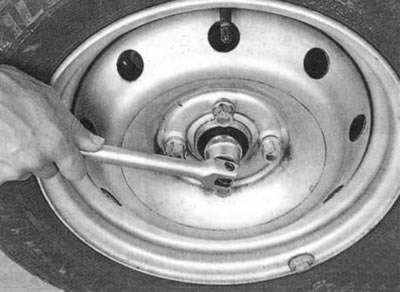
4. Loosen the hub nut and wheel mounting bolts.
Warnings:
- When loosening the hub nut, the car must be on the ground.
- Loosen and tighten wheel bolts only with the vehicle on the ground.
5. Apply the parking brake, place chocks under the rear wheels and lift the front of the car using reliable supports. Remove the front wheel.
Note: If your vehicle has anti-lock brakes, disconnect the wire harness connector from the wheel speed sensor.
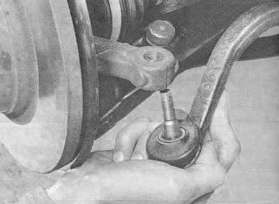
6. Disconnect the left steering rod from the steering arm (see "Replacing the outer tie rod end").
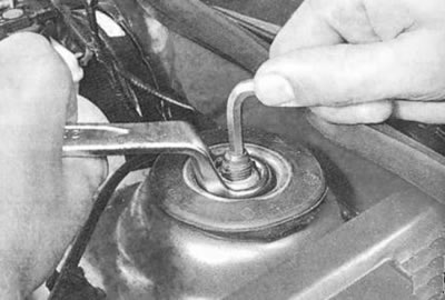
7. Loosen the shock absorber strut mounting nut (see "Removal and installation the shock absorber strut") and unscrew the nut to the end of the thread, but do not remove it.
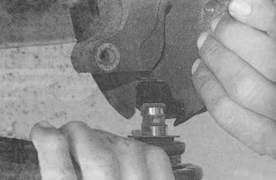
8. Disconnect the ball joint from the steering knuckle by pressing the lower arm down and overcoming the elastic resistance of the anti-roll bar (see "Replacing the front suspension arm").
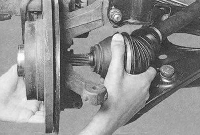
9. Move the shock absorber strut slightly to the side, while simultaneously removing the outer constant velocity joint tailpiece from the hub.
Helpful Hint: If you cannot remove the joint tailpiece by hand, knock it out of the hub with light hammer blows through a spacer made of soft metal or wood.
Warning: Be careful not to let the drive shaft come out of the axle gear as the joint rollers may fall into the transmission housing.
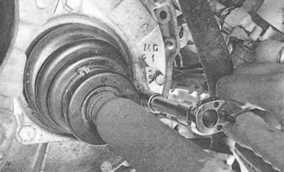
10. Remove the three bolts securing the inner drive joint boot holder to the gearbox housing...
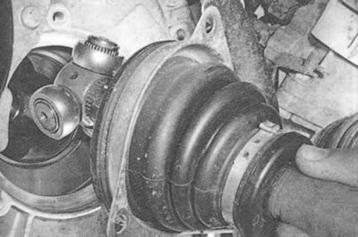
11. ... remove the inner joint from the slots of the axle gear and remove the drive.
Warning. When removing the joint from the axle gear, check with your hand how tightly the rollers fit on the journals of the three-pin joint hub. If they are loose, remove the drive carefully so as not to drop the rollers into the gearbox housing. Be careful when reinstalling the drive.
12. Install the left front wheel drive and all removed parts in the reverse order of removal.
13. After installing all the parts, fill the gearbox with oil (see "Checking the level and adding oil to a manual gearbox").
14. Install the wheel and screw in the mounting bolts until they stop, without tightening them completely.
15. Place the vehicle on its wheels, removing it from the supports, and tighten the hub nut.
Warnings:
- The hub nut should be finally tightened with the vehicle on the ground to a torque of 280 N·m (28 kgf·m). It is strictly forbidden to move the vehicle with the hub nut loose to avoid damaging the hub bearing separator.
- Do not reuse hub nuts.
16. Tighten the wheel mounting bolts (see "Wheel replacement").
17. Install the decorative wheel cover.
To remove the right front wheel drive, do the following.
1. Perform on the right side of the vehicle operations 1-9, which were performed on the left side to remove the left front wheel drive (see above).
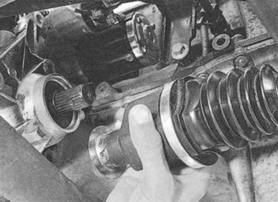
2. Slide the inner joint housing off the splined tailpiece of the axle gear and remove the right front wheel drive from the vehicle.
3. Install the right front wheel drive and all parts in the reverse order of removal.
Note: Before installing the drive, apply MOLYKOTE BR2 grease to the splines of the axle gear shank.
4. After installing all parts, fill the gearbox with oil (see "Checking the level and adding oil to a manual transmission").
5. Install the wheel and screw in the mounting bolts until they stop, without tightening them completely.
6. Place the vehicle on its wheels, removing it from the supports, and tighten the hub nut.
Warnings:
- The hub nut should be finally tightened with the vehicle on the ground to a torque of 280 N·m (28 kgf·m). It is strictly forbidden to move the vehicle with the hub nut loose to avoid damaging the hub bearing separator.
- Do not reuse hub nuts.
7. Tighten the wheel mounting bolts (see "Wheel replacement").
8. Install the decorative wheel cover.