



Only the internal hinges can be repaired by replacing parts. If the external hinges fail, they will have to be replaced completely together with the drive shaft, since the shaft is made in one piece with the hinge sleeve. During operation, it is possible to replace (with lubricant change) only outer hinge covers.
You will need: a snap ring puller or round-nose pliers with thin jaws bent at an angle of 90°, pliers with thin jaws, side cutters or a hacksaw for metal to remove the clamps that secure the covers, a punch, a hammer, a flat-blade screwdriver.
To repair the left front wheel drive inner joint, follow these steps:.
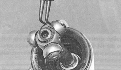
1. Remove the hub retaining ring by spreading it with a retaining ring plier or round-nose pliers and removing the ring from the shaft groove.
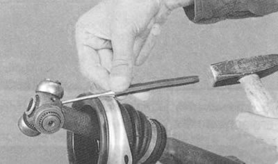
2. Slide the hub with rollers along the shaft splines...
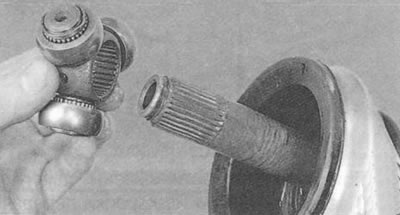
3. ...and remove it from the shaft.
Warning: Mark the position of the hub relative to the shaft and align it according to the marks when reassembling. If installing a new hub, orient it according to the marks on the old hub.
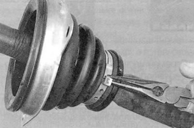
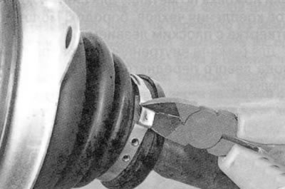
4. Remove the cover mounting clamp with pliers...
Helpful tips:
- The cover mounting clamp can be (and much easier) remove it by cutting it with side cutters, since the hinge repair kit necessarily includes a new clamp.
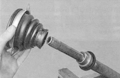
5. ...and remove the cover from the drive shaft together with its holder.
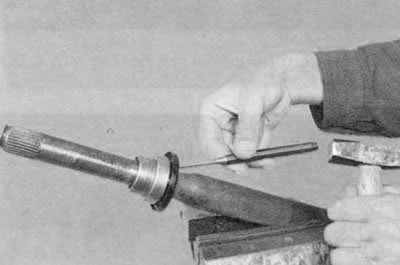
6. If it is necessary to replace the seal (in case of oil leakage from the gearbox) knock the bearing assembly of the boot off the shaft together with the seal and mud deflector.
Original publication on the website (renaultbook)
7. Press on using a suitable mandrel (it can be made from a pipe) a new bearing assembly on the shaft, maintaining the dimension (118±0.2) mm between the ends of the shaft and the bearing.
Warning: When pressing the bearing unit on, proceed carefully. To avoid damaging the bearing and seal, press the bearing unit on the shaft using a press, not with a hammer.
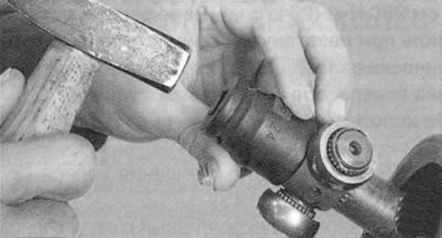
8. Install the cover on the shaft, secure it with a clamp, press the joint hub assembly with rollers onto the shaft splines (a suitable head from the tool kit can be used as a mandrel), aligning the marks made during disassembly.
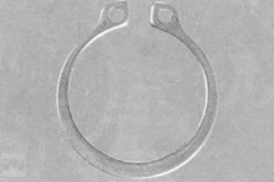
9. Install the retaining ring (see item 1). Make sure that the ring is fully inserted into the shaft groove.
To repair the right front wheel drive inner joint, perform the following:.
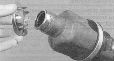
1. Remove the mudguard washer from the hinge housing tailstock.
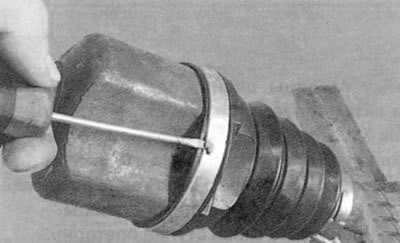
2. Remove the large cover mounting clamp by bending its tab with a screwdriver...
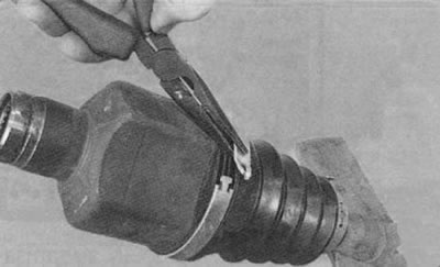
3. ...and grasping the clamp with thin-nosed pliers.
Helpful tips:
- To make it easier to remove the clamp, you can cut it with a hacksaw for metal, since a new clamp is always included in the hinge repair kit. When cutting the clamp, be careful not to damage the edges of the groove for the cover on the hinge body.
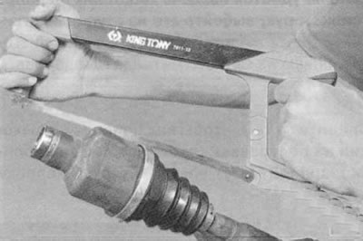
4. Similarly, remove the small cover mounting clamp.
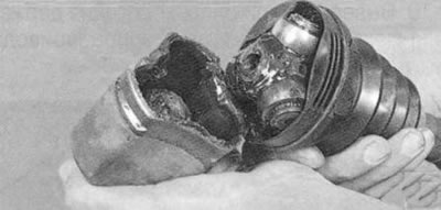
5. Remove the hinge housing.
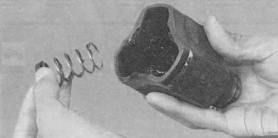
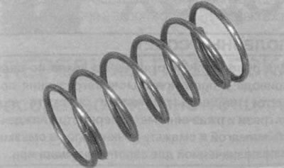
6. Remove the spacer spring from the housing.
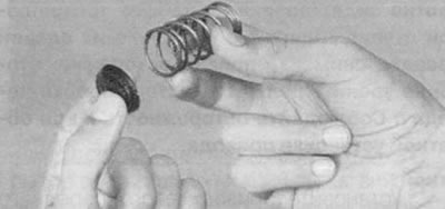
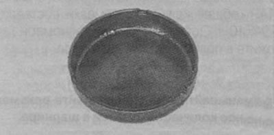
7. ...together with the thrust washer.
Note.
- Replace the deformed spring...
- ...and a thrust washer.
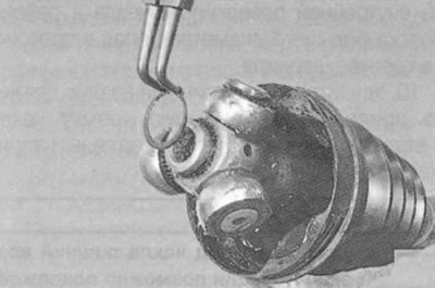
8. Remove the hub retaining ring by spreading it with a retaining ring plier or round-nose pliers and removing the ring from the shaft groove.
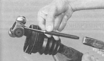
9. Slide the hub with rollers along the shaft splines...
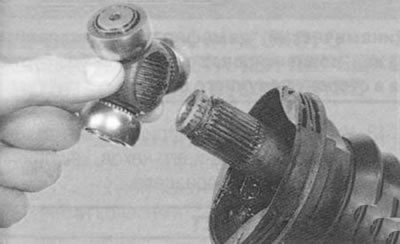
10. ...and remove it from the shaft.
Warning: Mark the position of the hub relative to the shaft and align it according to the marks when reassembling. If installing a new hub, orient it according to the marks on the old hub.
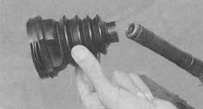
11. Remove the cover from the drive shaft.
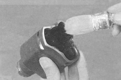
12. If the joint was disassembled only to replace the boot, remove the old grease from it by washing the inner cavity of the joint housing with kerosene or gasoline...
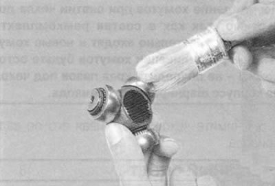
13. ...and the hub. Dry the parts with compressed air.
14. Install a new cover on the drive shaft. Make sure that the annular protrusion on the inner surface of the cover in the area of the small diameter belt fits into the groove on the shaft.
Helpful tips:
- To avoid damaging the joint cover during assembly, wrap the splined part of the shaft with insulating tape.
- To facilitate installation of the boot on the shaft, lubricate the shaft with a thin layer of grease designed to fill the joint.
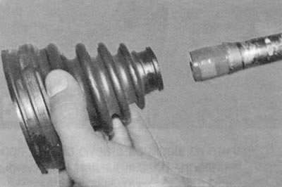
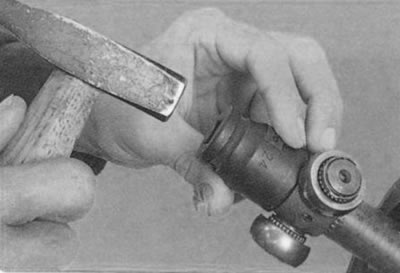
15. Press the joint hub assembly with rollers onto the shaft splines (a suitable head from the tool kit can be used as a mandrel), aligning the marks made during disassembly...
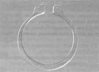
16. ...and install the retaining ring (see item 8). Make sure that the ring is fully seated in the shaft groove.
17. Place half of the required amount of MOBIL CVJ 825 BLACK STAR grease into the boot; the total amount of grease is (124±10) g. Place the remaining grease evenly into the cavity of the hinge housing.
Warning: Do not reduce or increase the recommended amount of grease in the joint.
18. Install the spacer spring and thrust washer into the cavity of the hinge housing (see paragraphs 6 and 7).
19. Install the joint housing on the rollers of the three-pin hub and put the joint boot on the housing. Make sure that the annular protrusion on the inner surface of the boot in the area of the large diameter belt fits into the groove on the joint housing.
20. Remove excess air from the cover by lifting the large edge of the cover and inserting a round rod, such as a punch, under it.
21. Without removing the rod from under the edge of the cover, move the hinge parts so that the distance between the ends of the small belt of the cover and the tail of the hinge body is 190 mm.
Note: If excess air is not removed from under the cover and the required hinge length is not set before securing the cover with clamps, the cover may be damaged during operation.
22. Without changing the position of the hinge parts, remove the rod from under the edge of the cover and secure the cover with clamps.
Warning.
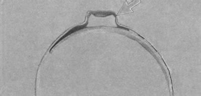
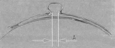
- This is what a new, "uncrimped" clamp looks like.
- The criterion for the correct "compression" of the clamp is the gap A. It should be within 2.4-2.8 mm. If the gap is larger, "press" the clamp to the norm; if less, replace the clamp.
23. Install a mudguard washer onto the hinge housing tailstock.
To replace the outer joint boots on both drives, follow these steps:.
1. Remove the inner joints and their covers from the drive shafts. In addition, when replacing the left front wheel drive cover, press the bearing unit of the cover together with the seal and mud deflector from the shaft, as described above in this subsection.
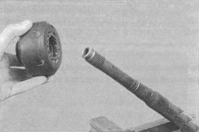
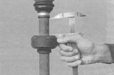
2. When replacing the outer joint boot of the right front wheel drive, additionally remove the dynamic damper from the drive shaft, overcoming the elastic resistance of the rubber mass of the damper.
Warning.
- Before removing the dynamic damper, measure and remember the distance between the ends of the damper and the hinge boot so that during reassembly you can install the damper in its original position.
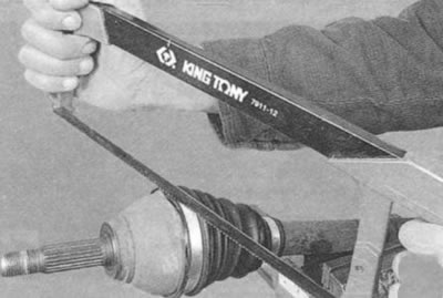
3. Remove the large...
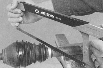
4. ...and the small clamps for fastening the cover, cut with a hacksaw for metal.
Note. Damage to the clamps when removing the boot is acceptable, as the hinge repair kit always includes new clamps. When sawing the clamps, be careful not to damage the edges of the boot grooves on the hinge body and drive shaft.
5. Remove the cover by pulling it along the drive shaft.
Helpful Hint: To make it easier to remove a damaged cover from the shaft, cut it with scissors or a knife.
Warning: To avoid damage to the hinge during operation, do not separate the hinge housing and the drive shaft after removing the cover.
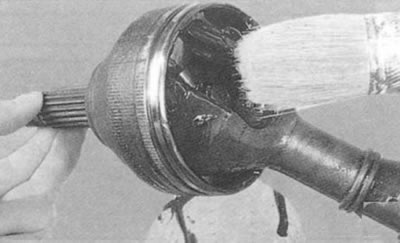
6. Remove old grease from the joint by washing its cavity with gasoline or kerosene, and dry the joint with compressed air.
Warning: Do not use solvents to clean the joint.
7. Install a new cover on the drive shaft. Make sure that the annular protrusion on the inner surface of the cover in the area of the small diameter belt fits into the groove on the shaft.
Helpful Hint: To make it easier to pull the boot along the drive shaft and to prevent contamination of the joint cavity, thoroughly clean the shaft from dirt and rust with fine-grained sandpaper and lubricate it with a thin layer of grease designed to fill the joint.
8. Place half of the required amount of MOBIL CVJ 825 BLACK STAR grease into the cover; the total amount of grease is (294±10) g. Place the remaining grease evenly into the cavity of the hinge housing.
Warning: Do not reduce or increase the recommended amount of grease in the joint.
9. Put the hinge cover on the housing. Make sure that the annular protrusion on the inner surface of the cover in the area of the large diameter belt fits into the groove on the hinge housing.
10. Remove excess air from the cover by lifting the large edge of the cover and inserting a round rod, such as a punch, under it.
Note: If excess air is not removed from under the cover, the cover may be damaged during use.
11. Remove the rod from under the edge of the cover and secure the cover with clamps.
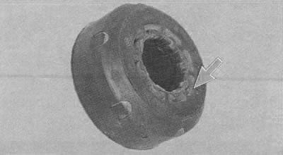
12. To drive the right front wheel, install a dynamic damper on the drive shaft, maintaining the distance measured before disassembly between the damper and the joint boot.
Note.
- Install the dynamic damper on the shaft, orienting it with the end without the flange towards the outer hinge.
13. Install all the inner joint parts and its boot onto the drive shaft as described above in this subsection.
Helpful Hint: To increase the service life of the inner joint of the right front wheel drive, replace the grease in it with fresh grease as a preventative measure.